Showing posts with label blog. Show all posts

Sunday, September 18, 2016

Plant Design: Motor Protection Parameters

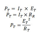
The table below is an example of a working protection parameters of an electrical system. A parameter sheet such as this will enable the designer to tabulate necessary initial values and  calculations.

NO.
Equipment name
Nominal power
(kW)
Circuit calculation current(A)
CT trans. ratio
Zero sequence CT trans. ratio
Circuit type
1
Motor Pump No.1
3400
355.6
1000/1
2000/1(Differential)
100/1
Vacuum breaker
2
Motor Pump No.3
1400
146.4
500/1
100/1
 Vacuum breaker
3
Motor Pump No.3
1000
104.6
400/1
100/1
Vacuum breaker
4
Motor Pump No.4
400
41.8
200/1
100/1
F-C circuit
5
Motor Pump No.5
900
94.1
300/1
100/1
F-C circuit
6
Motor Pump No.6
710
74.3
200/1
100/1
F-C circuit

First is to work out in calculating the circuit current of a three phase motor circuit:

Circuit Current=kW/(√3∗kV∗pf )

Instrument and protection CTs are governed by standard IEC 60044-1 . The matching of CTs with protection relays calls for a thorough knowledge of CTs. The following section gives a few reminders in determining   the CT ratio, the table below will give the recommended primary CT ratio for various circuit current in the  motor protection  section. See (link) for complete list of CT ratio per application.

CT Primary=kW/(√3∗kV∗pf *η )


If you do not know exact values for Ï• and η as a first approximation, you can assume that: cos Ï• = 0.8 ; η = 0.8. T. The secondary circuits of a CT must be suitable for the constraints related to its application for  or protection purposes.

CT Secondary  
For use in a local situation Isn = 5 A
For use in a remote situation Isn = 1 A

The use of 5 A in a remote situation increase the cross section of the line or the sizes of the transformer (lost in line). IEEE C57.13 Table 8 - Standard multi-ratio current transformer taps gives the standard ratings for instrument transformers. Sequence CT Ratio are constant 100/1 in 4.160 and 6.9kV Circuit.

For the circuit Type in 6.9kV , there are two recommended circuit types. Use  Vacuum Circuit when the Current reached above 100 Amps or Fused Contractor when dealing with currents below 100 Amps.

Monday, June 13, 2016

Generator excitation control operation

Increasing the output voltage of a generator is achieved by adjusting the magnitude of the excitation current. This happens because as DC current is increased, the rotating magnetic field increases thereby increasing the generator  voltage induced in the stator conductor.     As the voltage is increased, the generator will transfer more MVAR into the power system.
Instead of collector rings, suppose that a  brushless generator above  is used in our example. The exciter is provided from the DC winding which is wound in the stator. The rotor produces ac current that is feed into the rectifier built in the shaft. The rectifier converts AC to  DC and feed the rotor windings.

To control of the rectifier  output in the field windings of the excitation generator, voltage regulator receives its command signal from the AC voltage controller which monitors the ac voltage of the monitor.


The limitation of the generator due to current in the stator should follow within the machine capability curve. Increasing the excitation current of the generator to deliver MVAR will produce heating in rotor winding. alternatively, if the excitation is reduced voltage and VARS will fall. then the machine will have weak magnetic field .

Technical Data for Generator 60WX18Z-090 with Static Excitation 158,8 MVA 13800 V 60 Hz p.f. = 0,85 Tcg = 33 °C Temp.-Cl. = 130(B
In the capability curve, the horizontal axis is the  reactive power in per unit quantity, where 1 pu =159 MVAR and the vertical axis is the active power per unit quantity.

Monday, April 2, 2012

EEWeb Website of the Day April 2, 2012

This blog is featured in EEWeb - Electrical Engineering Community, as website of the day for April 2, 2012. This is an excellent recognition from a popular electrical engineering community website for hardware engineers. I'm happy and honored that this blog was on the front page of the EEweb  and was included in the list of impressive websites  that EEweb has recognized in the past.

Thank you EEWeb!

Update: 2013
The old name of this website was "Mathematics and Engineering Topics" and now changed  to "EngineerMaths.com". The change was due to transfer of this website from free domain to a premium domain name. Every articles and feeds will be automatically redirected  into our new domain. For example, when you visit our old address [Mathematics and Engineering Topics], it  will redirect you to our new address.

Screenshot of Enginering and Mathematics Topics in EEweb


Screenshot of EEweb home page

Wednesday, March 28, 2012

Electronic Control of automatic Recloser

Electronic Recloser Contol is compromised of a number of programmable, solid solid-state electronic circuits that perform the command fuctions involved in automatic recloser operation. It is used to operate all electronically controlled reclosers.
the control panel of the control unit contains the programming and opening elements of the control.

Parts of the control panel of the electronic recloser:
Minimum trip resistors - Establish the minimum trip current levels for ground and each phase; cartridges are marked in primary amps and clamped in place.
Operation counter - record the cumulative trip operations of the control.
Sequence relay - steps the control through its operating sequence.
Ground- Trip Operation Switch -Blocks all ground in the BLOCK position: prevents unintentional tripping during single -phase switching operations.

control panel of electronic recloser
Recloser Control panel

Manual Control Switch - In the TRIP position, it locks out the control, advances the sequence relay lockout, and disconnects the battery from the control circuits. In the CLOSE position, it moves the sequence relay to the home position, reconnects the battery and closes recloser. If held in CLOSE position, it will override cold- load inrush ; however, the control will lockout for permanent faults.
Control Fuse- Protects the closing solenoid coil (on reclosers that employ solenoid closing)  if closing voltage is too low. connected in series with the closing contactor in the recloser on motor- operated units; connected in series with the contactor rotary solenoid on reclosers that  employ solenoid closing
Non- Reclosing Switch - Sets the control  for one shot to lockout without disturbing the lockout setting of the operations selector.
Lamp Test Lockout Switch - Enables testing the signal  lamp and checking for lockout.
Lockout Indicating Signal lamp - Provides visual indication of control lockout
Battery Test Tetminals - Enable checking battery voltage, charging rate ,and quiescent current drain.
Reset -Delay Plug - Determines the delay interval before the control resets after a successful reclosure during an operation sequence. the delay value is determined by position of the plug in socket adapter.
Phase Trip Timing Plugs - Provide a variety of current integrated timing curves on individual plugs for coordinating the phase trip operation with backup and downline protective devices.
Ground Trip Timing Plugs -Provide a variety of current integrated timing curves on individual plug for coordinating the ground-trip operation with backup and downline protective devices.
Reclosing  Interval Plugs - Determines the delay interval for each closing operation. The delay value is determined by the position of the plug in the socket adapter. An instantaneous plug is available for the first reclose interval only.
Phase Trip Selector - Programs the number of fast phase trip operations as defined by the timing pug in Socket 1; the remaining (slower) operations to lockout are defined by the plug in phase trip socket 2
Lockout Selector - Programs the total number of operations to lockout.
Ground Trip Selector-  Programs the number of fast ground trip operations as defined by the timing plug in socket 1; the remaining (slower) operations to lockout are defined by the plug in ground trip socket 2

Automatic Circuit Recloser

Recloser is a device that is used in over head distribution systems to interrupt the circuit to clear faults. Automatic reclosers have its electronic control senses and vacuum interrupters that automatically recloses to restore service  if a fault is temporary. There are several attempts that may be made to clear and reenergize the circuit and if the fault still exist the recloser locks out. Reclosers are made in single-phase and three-phase versions, and use  oil or vacuum interrupters.

Operation
Systems where a SCADA control interface capability is required in the use of automatic reclosers. The controls for the reclosers range from the original electromechanical systems to digital electronics. The operating sequence of all the reclosers can  be all fast, all delayed or any combination of fast followed by delayed up. Fast operations clear temporary faults before branch circuit line fuses are weakened. Delayed operations allow time for down time protective devices to clear so that permanent faults can be confined to smaller sections of the system.
automatic circuit recloser
Three Phase Vacuum Circuit Recloser
image credit: www.abb.com  
A complete electronic recloser package consists of the recloser which interrupts the circuit, an electronic control which senses over-currents and actuates the recloser and an interconnecting control cable.

Tripping and Closing
Recloser tripping and closing are initiated by signals from the electronic control. When fault currents in excess of the programmed minimum-trip value are detected in one or more phases, a signal from the control actuates a low energy tripper in the operating mechanism of the recloser to trip the opening springs and open the interrupter contacts. Closing energy and the force required to charge the opening springs is supplied by a high-voltage closing solenoid momentarily connected phase-to-phase through a high-voltage contactor.  At the programmed reclosing time, the control energizes a rotary solenoid in the operating mechanism which mechanically closes the closing solenoid contactor to connect the closing coil to its power source.  The energized closing coil pulls a plunger down, charging the opening springs.

Saturday, February 18, 2012

AC Circuit Phase Sequence

Phase sequence is the order in which the generated voltages in the phase winding of an alternator reach or  attain  their peak or maximum values. It is represented by the letters a, b, and c or the numbers 1, 2, 3 or by using double letter as ab, bc  and ca or  an, bn  and cn.

For instance , The three phase balanced voltages with their common magnitudes as K have sequence of a b c , then in complex form, 

Positive Phase Sequence 
ABC sequence  -  Va = Ka0˚ , Vb = a-120˚ and Vc = Ka-240˚

In this sequence Vb lags Va by 120˚ and Vc lags Vb by 120 or Vc lags Va by 240. The maximum value of Va comes first in the positive direction, next Vb and then Vc. 

ABC →BCA →CAB
AB - BC - CA → BC - CA - AB → CA - AB - BC
AN - BN - CN → BN - CN - AN → CN - AN - BN

Vector Representation

ABC Phase Sequence
 Sequence ABC  


BCA Phase Sequence
Sequence BCA
CAB Phase Sequence
Sequence CAB


Negative Phase sequence 
ACB sequence- Va = Ka0˚ , Vb = a-120˚ and Vc = Ka-240˚

Voltage Vc lags Va by 120˚ and voltage Vb lags Vc by 120˚

ACB →CBA →BAC
AB - CA - BC → CA- BC - AB → BC - AB - BA
AN - CN - BN → CN - BN - AN → BN - AN - CN

Vector representation
BAC Phase Sequence
Sequence BAC
CBA Phase Sequence
Sequence  CBA

ACB Phase Sequence
Sequence ACB

Assume a positive phase sequence if the phase sequence is not given . The three  phase alternators are designed to operate with positive phase sequence voltages.

Tuesday, January 17, 2012

Balanced Three phase AC circuit Delta connected

A balanced three phase AC circuit systems is energized by three equal alternating emf's of the same frequency but 120 degree apart. The phase impedance are equal. Also the currents are equal and 120 degree apart.
Three AC emf's differing in time phase by 120 degree
DELTA (MESH) CONNECTED SYSTEM
This type of connection is reffered to as 3 phase, 3 wire system. In this connection , the dissimilar ends of the 3 phase windings of a 3 phase ac generator are joined together,  for example the starting ends of one phase is joined to finishing end of the other phase so on. In other words the three winding's are joined in series to form a closed mesh. three leads are taken out from the juntions to serve as the generator terminals.
Delta mesh connected system
Delta connected System
Relationships: VØ = VL       :  IØ = IL/(3)   
 Where:
        VØ  - phase voltage
        IØ  - phase current
       VL -  line voltage
       IL -  line voltage

The three phase voltages of this circuit always sum to zero  Va + Vb + Vc =0

As seen from the diaram, there is only one phase winding completely included between any pair of terminals. Hence, in delta connection, the voltage between any pair of lines is equal of the phase voltage of the phase winding connected between the two lines considered.

Monday, January 16, 2012

Electronics :Traffic light Circuit


This is a two way continuous traffic light circuit which uses  LED, diodes and IC's . 
Usually most traffic light in the world is PLC controlled but this circuit is  simple  and easy to build . 

 In the image below is the schematic diagram of the project . I used Yenka Free Software to simulate and see if its properly working . You can download it free on Yenka website.

two way 555 traffic light circuit

The  clock pulses from the 555 astable circuit is sent into the 4017 decade counter . Each output becomes high in turn as the clock pulses are received. Appropriate outputs are combined with diodes to supply the amber and green LEDs. 
simple 2-waytraffic light circuit
components :
  • resistors: ,50k ohm, 10k ohm, two-100k ohm
  • capacitors: 10µF 16V radial
  • diodes:  16 pieces of 1N4148 
  • LEDs: 2 sets of ( red, amber or yellow, green)
  • IC:555 timer ,  4017 counter
  •  on/off switch
You can adjust the timing of light-shifting by adjusting the  value of the resistor in the astable circuit . 

Friday, December 10, 2010

RLC parallel circuit formula and Phasor diagram

RLC in parallel


RCL parallel circuit can be considered as two reactance's XC and XL where the currents are in phase opposition in parallel with the resistor.
 parallel RLC circuit connection
Through the use of  the phasor diagram the effective total resistance can be found  . It can be observed that IR is at the base of the right triangle and IL minus IC minus IL forming the perpendicular.
The amplitude of the resultant current is the hypotenuse.
 parallel RLC phasor diagram

To calculate the resultant we use the Pythagorean theorem . Ic and IL  are 180 degree out of phase  therefore cancel out. The resultant current is the difference between the two.

RLC parallel connection formula current calculation


Impedance  phase angle  is calculated from the difference between IL and IC divided by IR

Parallel RC circuit formula and phasor diagram

RC circuit in parallel formula and diagram
Parallel RC circuit connection diagram
Currents in IR and IC are 90 degree out of phase and cannot be added directly. The total current or resultant will depend upon the resistance and R and the reactance ( AC reactance) of AC

Parallel RC circuit Phasor diagram :
Parallel RC circuit phasor diagram


As the reactance of C falls relative to resistance of R , so more current flows in the capacitor branch and the resultant phase angle increases

Parallel RC circuit formula :
Parallel RC circuit formula


Parallel RL circuits formula and Phasor diagram explanation

Parallel  RL circuit formula and diagram


Parallel RL circuits connection diagram

The current through L will lag  IR  by 90 degrees . The resultant negative phase angle  depends upon the relative values of R and XL. for R, E and R in phase . For  XL , E and IL in quadratic lagging current.
As  the circuit is inductive the phase angle is  negative.

Parallel RL circuit Phasor Diagram
Parallel RL circuit phasor diagram

There cannot be a direct addition of IR and IL because of their 90 degree phase angle. 

Parallel RL circuits formula

Parallel RL circuit formula

Parallel RL circuit formula proof


Thursday, December 9, 2010

Series RLC circuit formula explanation

Series RLC circuit diagram and formula
Series RLC  connection Diagram


Resistance ,inductance capacitance in series
  
formula resistance, capacitance and inductance in series


In RLC series circuit , the series current is common for Resistance, Capacitance and inductance . VR will be in phase width I. Whereas the voltage of Vc and VL will be 180 degree phase opposition, resulting in some cancellation.

Series RLC  Phasor Diagram
Series RLC phasor Diagram
The phasor diagram will produce the resultant circuit voltage and its phase angle. Positive angle indicate a greater inductive circuit influence and negative angle capacitive.

This is the corresponding formula for RLC circuit
Series RLC formula's


Series RLC Formulas

The formula for Series RC circuit with Phasor Diagram

Series RC circuit formula explanation

Series RC circuit diagram connection


 R- the resistance -opposition to current flow (ohms)Ω
C- capacitance-opposition to any change in voltage ,farad(f)
 VR=IR- voltage drop of the resistor
Vc= q/c=∫idt/c- voltage drop in the capacitor
     
     When a capacitor and a resistor  are in series current will flow to charge the capacitor .
 The two voltages VR and VC cannot be added directly and the phasor diagram is used  to find the resultant or the applied voltage amplitude and phase angle . 

Voltage VC can be found using Ohms law where VC = XC x I
The resultant or applied voltage is that which or developed across the circuit with these particular component values.  The resultant voltage can be greater than the individual values of VR and Vc   

As this is capacitive circuit the resultant voltage angle will lag the current I
Current I is shown as being in phase with VR . VC will lag I by 90.

Series RC circuit Phasor Diagram
series RC circuit Phasor diagram
Series RC circuit Formula
series RC circuit formula

Here are the Formulas and the proof solution for the formula in RC circuit:


series RC circuit formula proof solution

Series RC circuit Waveform
This is an example of a waveform produced by the   resultant voltage and corresponding resultant phase  angle.
series RC circuit generated waveform


Analyze the formula for Series RL circuit and its Phasor Diagram

   Series RL circuit
series RL circuit diagram

R- the resistance -opposition to current flow (ohms)Ω

L- Inductance -opposition to any change  
XL- inductive resistance
VR=I R volts
VL=I XL volts
XL = inductance reactance  (ohms) Ω
      = 2Ï€fL= ωL


Voltage developed across R and L cannot be added directly. The phasor diagram is used to show the resultant voltage and phase angle.The resultant or the applied voltage will lead the current I which is given an arbitrary value in the instance to show that is in phase with VR

Phasor diagram Series RL circuit:
series RL circuit phasor diagram

Series RL circuit Formula :
Series RL circuit Formula proof

Series RL Circuit generated Waveform:
The larger the relative value of the  XL to R the closer the resultant phase angle willl be 90 degrees which is an indication of the amount of inductance in the circuit.

series RL circuit generated waveform

Tuesday, November 30, 2010

Power in parallel Circuits

Power dissipated by each individual resistance is simply added to find the total power dissipated by the series circuit. This same procedure also applies to parallel circuits. If there are five resistive branches in a parallel circuit and each was dissipated 1 watt of power, the total power the circuit is 5 watts . The individual power dissipations of all resistors are added to find the total power dissipated.

Pt= P1+P2+P3....+Pn


Pt=1W+1W+1W+1W+1W=5W

power Calculations in parallel Circuits

power in parallel circuits formula


Where: I-current
            E-voltage
            R-Resistance


As an alternative method ,If you have already calculated the total or main line currents flowing in the circuits, the total circuit voltage,and /or the total circuit resistance, you can calculate the total power the circuit dissipates by using the three formulas listed above on the total circuit quantities.

alternative method power in parallel circuit


where:
It-total current
Et-Total voltage
Rt-Total Resistance
Pt-Total power

Monday, November 29, 2010

Series and parallel resistance circuit :explanation

The familiarity of the few circuit building blocks is important in  understanding complex circuits. In this post I will explain the most important ideas in  DC circuits.

From my previous posts I discussed about the Ohms law . This is a continuation of the post about  simple direct current circuits. 
   
Resistors in series
   A series circuit is one in which total line current passes through each and every conductor in the circuit. two or more electric component are considered to be in series in the same current flows through all these component
resistors in series diagram


laws of Series circuit
1. current in all parts of the series circuit is the same
It=I1+I2+I3+In
2. voltage across a group of conductor connected in series is equal to the sum of the individual voltage across individual resistors
Et=E1+E2+E3+En
3. total resistance of a group of conductors connected in series is equal to the sum of the individual resistances
Rt=R1=R2+R3+Rn

Resistors in parallel
  A parallel circuit is one in which current may flow through two or more independent branches.Two or more components are considered in parallel if the same voltage appears across all these components

resistors in parallel diagram


laws of parallel circuits
1. total voltage of a parallel circuit is the same as across each branch of circuit
Et= E1=E2=E3=En
2.Total current is equal to the sum of individual branch currents
It=I1+I2+I3+In
3.The reciprocal of the total resistance of a number of resistors connected in parallel is equal to the sum of the reciprocals of the separate resistances.Total resistance is always less or approximately equal to the values of the smallest resistive branch
1/Rt=1/R1+1/R2+1/R3+1/Rn
 Rt=1/(1/R1+1/R2+1/R3+1/Rn)

Note that : it is important to know that connecting additional resistors in series increases resistance, while connecting additional resistance in parallel decreases the total resistance.