Series RL circuit

R- the resistance -opposition to current flow (ohms)Ω
L- Inductance -opposition to any change
XL- inductive resistance
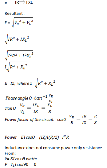
VR=I R volts
VL=I XL volts
XL = inductance reactance (ohms) Ω
= 2πfL= ωL
Voltage developed across R and L cannot be added directly. The phasor diagram is used to show the resultant voltage and phase angle.The resultant or the applied voltage will lead the current I which is given an arbitrary value in the instance to show that is in phase with VR
Phasor diagram Series RL circuit:

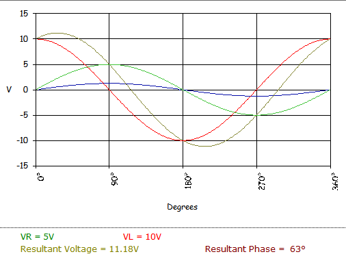
Series RL Circuit generated Waveform:
The larger the relative value of the XL to R the closer the resultant phase angle willl be 90 degrees which is an indication of the amount of inductance in the circuit.