Tuesday, November 30, 2010

Power in parallel Circuits

Power dissipated by each individual resistance is simply added to find the total power dissipated by the series circuit. This same procedure also applies to parallel circuits. If there are five resistive branches in a parallel circuit and each was dissipated 1 watt of power, the total power the circuit is 5 watts . The individual power dissipations of all resistors are added to find the total power dissipated.

Pt= P1+P2+P3....+Pn


Pt=1W+1W+1W+1W+1W=5W

power Calculations in parallel Circuits

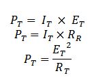
power in parallel circuits formula


Where: I-current
            E-voltage
            R-Resistance


As an alternative method ,If you have already calculated the total or main line currents flowing in the circuits, the total circuit voltage,and /or the total circuit resistance, you can calculate the total power the circuit dissipates by using the three formulas listed above on the total circuit quantities.

alternative method power in parallel circuit


where:
It-total current
Et-Total voltage
Rt-Total Resistance
Pt-Total power

Monday, November 29, 2010

Series and parallel resistance circuit :explanation

The familiarity of the few circuit building blocks is important in  understanding complex circuits. In this post I will explain the most important ideas in  DC circuits.

From my previous posts I discussed about the Ohms law . This is a continuation of the post about  simple direct current circuits. 
   
Resistors in series
   A series circuit is one in which total line current passes through each and every conductor in the circuit. two or more electric component are considered to be in series in the same current flows through all these component
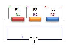
resistors in series diagram


laws of Series circuit
1. current in all parts of the series circuit is the same
It=I1+I2+I3+In
2. voltage across a group of conductor connected in series is equal to the sum of the individual voltage across individual resistors
Et=E1+E2+E3+En
3. total resistance of a group of conductors connected in series is equal to the sum of the individual resistances
Rt=R1=R2+R3+Rn

Resistors in parallel
  A parallel circuit is one in which current may flow through two or more independent branches.Two or more components are considered in parallel if the same voltage appears across all these components

resistors in parallel diagram


laws of parallel circuits
1. total voltage of a parallel circuit is the same as across each branch of circuit
Et= E1=E2=E3=En
2.Total current is equal to the sum of individual branch currents
It=I1+I2+I3+In
3.The reciprocal of the total resistance of a number of resistors connected in parallel is equal to the sum of the reciprocals of the separate resistances.Total resistance is always less or approximately equal to the values of the smallest resistive branch
1/Rt=1/R1+1/R2+1/R3+1/Rn
 Rt=1/(1/R1+1/R2+1/R3+1/Rn)

Note that : it is important to know that connecting additional resistors in series increases resistance, while connecting additional resistance in parallel decreases the total resistance.

Sunday, November 28, 2010

What are Motor controls and how they work

Motor controls a quick summary 
     Motor controls are those devices that operate electric motor particularly, those high powered electric motors used to operate machines like electric drilling machines, wood lathe machine, electric bending machine and those other machine used in the industry plant.
Motor controller


Motor controls can be divided into three major types;
1. Manual- The construction of the controllers here constitutes  only simple devices requiring the  operator  to go into the controller location to initiate the change in the state of the control system. the installation of the controller to the motor is simply done by connection of the switch in series withe the motor.

2. Semi-automatic-This type of controller is characterized by the use of push button, pressure switches , limit switches and other sensing devices to control the operation of magnetic contactor or starter. The operator must still initiate some actions such as starting and stopping but he does not have to go the location of the motor or the starter to perform the operation.


semiautomatic motor controls

3. Automatic- Similar to semiautomatic, an automatic controller  is characterized by the use of sensing devices.With an automatic control, the operator doest have to initiate certain actions. After that the operation is set , the system will continue to operate in its own.

Semi-automatic and automatic controllers are generally employed with an overload or low voltage release protection to shut down the system automatically for protection of the device and the operator.

     Motor Controls involves the use of the following devices like magnetic starters and push button station and  the use of cables to connect this devices. This cables maybe any of the following, BX cable ,loomex cable,steel conduit wiring.For push button stations it can be a start-stop, forward-reverse-stop push button and the start-jog-stop push button. For Push button types it can be a normally open or closed push button,stacked push button, push pull buttons and lighted push buttons. Push buttons  can make or break the connection in a control system.

Motor Controls are divided into the following
1.Motor controls for alternating current (AC)machines or motors
2 Motor controls for Direct current (DC) machines or motors

Saturday, November 27, 2010

A review Complex number

Complex number review 

   Complex number are usually discussed in the first part of advanced mathematics and here is a quick review about it.

Consider the equation
no solution equation in real number system
it has has NO SOLUTION in real number system.

complex number i or j
But in eighteenth century mathematician invented a   new number  "i"  which is defined by the property. this in turn , led to the development of complex numbers, which are numbers of the form a+bi .
   "a "and "b" are real numbers. But it can be also observed that every real number a is also a complex number because it can be written as a=a+0i. Thus ,the real numbers  are a subset of the complex numbers.

With these properties complex number can be now defined as.
---the combination of real and imaginary number which can be expressed in the form a+bi or a+jb where i or j=-1


Powers of i or j


powers of i or j
Note for  j^n
If n is divided by 4 and the result is 1 it follows j^4. if the result has a decimal value of (.75) if follows j^3.If (.50) it follows  j^2. If (.25) it follows j


Argand's diagram
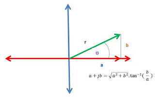
argand's diagram


real axis


Forms of complex numbers -complex number can be expressed in different notations.
1.) rectangularr form  -complex number is denoted by its respective horizontal and vertical components.
         a+jb                              where:   a-real value
                                                          jb-imaginary axis 

2.) polar form - complex number can be denoted by the length  and the angle of its vector
         rÆŸ                                          where: r- magnitude
                                                                      ÆŸ - argument,degrees
3.) trigonometric form
           rcosÆŸ  +jsinÆŸ                     where: r-magnitude
                                                                    ÆŸ-argument,degrees
4.) Exponential form
complex number exponential form
                                            where: r-magnitude
                                                      ÆŸ-argument,degrees


Friday, November 26, 2010

How are coils connected in an alternator ?

Alternator coil connections
  There are two ways of connecting the coils of the three phase AC generators  or alternator in a load. These are the wye or the star connection and the delta connection. Generally, generators are wye connected ( earth wire) but loads can be either delta or wye.

1. Star Connected, 4-wire Alternator
                                               iA
Star connected 4 wire alternator


iC


iB


This takes advantage of the fact that the sum of the three phase  current is zero
          iA +iB iC =0

When the generator has a balanced output and the loads connected to each phase are identical then the calculation of the voltages and current for, say the red phase can be applied equally to two other phases. The voltage in A,B,C are called phase voltages and are the potential difference developed between Vab, Vbc, Vac


2. Delta connected, 3-wire Alternator
    In this configuration the connection has no neutral line. The voltage between pair of lines are equal to the phase voltage of the generator and the line current is the  difference between the two phase currents.
    The line currents are the currents flowing into and from the load where the actual current is the addition of the two.
   For balanced poly-phase systems phases have  identical line voltages and currents.
border=
 iA  


iB


iC


delta connected alternator formulaThis takes advantage of the fact that the tree phase voltages always sum up to zero

          Va+Vb+Vc=0


Sources
Electrical engineering training series :Three phase alternator connection
Network analysis 2007

Thursday, November 25, 2010

Transformer operation and construction

Transformer: Basic operation and construction
  Transformer is an electrical device that converts voltage from one value to another that is, either from high voltage to lower voltage which is termed step- down transformer, or from lower voltage to higher voltage which is termed step up transformer. 


 The principle behind lowering or raising the voltage  is done through  magnetic induction between its coils. Changing current in the primary winding  creates  alternating magnetic field in its the core.  And  as the core multiplies this field and couples the most of the flux through the secondary transformer windings, It   creates an induction of alternating voltage or the electromotive force in each of the secondary coil.


Core type transformer
A transformer is constructed with the following essential parts  :

1. Core (iron core or air core)
2. Windings ( primary winding or secondary winding)
3. Insulation (major insulation and minor insulation)
Transformer parts and function
The core is  made up of  of lamination   sheets. one of the best  used as core is silicon steel
 These sheets has its purpose:

a) to hold the windings in place
b) to serve as path for  magnetic circuit  or magnetic field
 The lamination sheets are pressed tightly together leaving no spaces between sheets.


  Another essential part of the transformer are the windings. Windings are made up of copper wire generally termed as magnetic wires. These wires are usually covered with varnish insulation. Other magnetic wires beside the varnished insulation are still covered with cotton and generally used for big transformer.
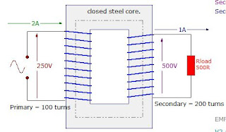
Transformer winding arrangement  Windings are composed of primary and the secondary winding. The primary winding is the one that is connected to the power supply , the purpose of which is to get the required power. On the other  hand, the secondary winding is the one connected to load and deliver the needed power. The secondary maybe one or more windings.


  The insulation is used to separate or insulate iron core as well as the windings. There are two types of insulation used in transformer,
a.) major insulation
b) minor insulation. the major insulation is used to insulate or separate the windings from the iron core and insulate or separate the primary winding from the secondary winding. The minor insulation on the other hand is used to insulate or separate one layer of turns to the  next layer.

Transformer Operation
  When the primary winding is plugged or connected to the power source, magnetic lines of force are developed around the windings and travels within the iron core. By electromagnetic induction principle, these magnetic lines of force travelling around the core induces another voltage to the secondary windings which gives the idea although the primary and the secondary windings are separated or not connected to each other, a lower or higher voltage can be produced in the secondary winding. in this operation of transformer, one must recall his knowledge of the principles  of electromagnetic induction.

Sources

Electrical Transformers Explained  How Is Electric Energy Produced

Tuesday, November 23, 2010

ENGINEERING SOLUTIONS

ENGINEERING SOLUTIONS
I came across this blog just recently and I find this one very informative.This blog provides fresh graduates specially mechanical engineering, find a job in well reputed company . Tips and guidance published here will surely educate you in dealing with job interview.

Polyphase system: How Three phase sytem works?

Three Phase system

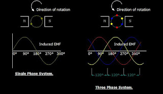
   A three phase circuit is energized by three alternating emf's of the same frequency and differing in time phase by 120 .The emfs are generated in three sets of armature coils in an ac generator. These three sets are 120 degree apart on the generator armature. The coils may all be brought of the generator to form three separate single phase circuits. however the coils are ordinarily interconnected either internally or externally to form  a three-wire or four wire system.

AC 3 three phase system
shows the generation of induced emf in 3 spaced coils with 120 degree phase difference
    The voltage in red coil  reaches a maximum cycle first,followed by coil in yellow, and then coil in blue for sequence ABC.The figure also shows the sine wave developed as the coil rotates.

the voltage phase sequence of the three phase system can be determined by the rotation of the alternator coils. At  counterclockwise rotation of the coils, the phase sequence is ABC. The opposite rotation gives the sequence CBA


Monday, November 8, 2010

Introduction to Ohm's law

                                                   
What is Ohm's Law ?
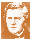
Georg Simon Ohm

In 1826 Georg Simon Ohm discovered that for metallic conductors there is substantially constant ratio of the potential difference between the ends of the conductor.
  Ohm's Law states that the current flowing in an electric circuit is directly proportional to the applied voltage and inversely proportional to the resistance of the material.
ohm's law equation
Ohm's Law equation
  
I- current
V-voltage
R- resistance


Ohm's law is explained by the following statement.

1. Current varies directly with applied voltage
    A change in the voltage applied to a circuit will  cause the current flowing in the circuit to change.  If the resistance is  constant, the current change will follow the pattern of the voltage change.  Doubling the potential difference doubles the current.

2. Current varies inversely with resistance
   Changing the resistance in a circuit will also cause a change in current flow. if the voltage applied to a circuit is held constant, and the resistance in the circuit is increased. With more opposition to current  flow in the circuit, the circuit current will decrease. On the other hand, if the resistance is decreased the amount of current flow in the circuit will be increased.


3. Voltage vs. current
voltage vs current graph
   The  relationship between voltage
and current can be graphically
 represented with this illustration.

thus:
  1. the higher the voltage, the larger the current
  2.the higher the resistance the lower the current

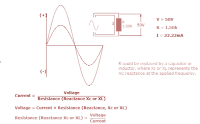
         AC Ohms Law
AC Ohms Law


Ohms law can also be applied in AC circuits.But alternating voltage and currents are always changing. From zero, current and voltage builds up and reach  its max peak in the positive value at 90 degrees and then back to zero and again to the negative peak value.
In this regard, Its only possible to calculate instantaneous values of voltage and current throughout its cycle.
For AC Ohms law can be expressed by the the same  equation , where R could be replaced by a  inductor or capacitor , where Xc or XL is the AC reactance
Ohms law circle form


Ohms Law Derived formulas formulas from 
Ohms law circle

V= I x R
I=  V/ R
R= V/ I


Saturday, November 6, 2010

Generators in parallel

Why generators are in parallel?
here are some of the summarized  reasons:

1. Continuity of the service
2. Efficiency
3. maintenance and repair
4. Addition to plant ( provision or future expansion)
.
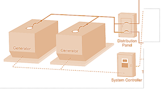
Parallel generator operation

Efficiency
In an electrical power generating system  the load fluctuates, usually reaching a minimum  during the night and having its peak value during day time.And with several machines required to supply the load, it becomes necessary to operate them in parallel so that their combined outputs may be transmitted from the same bus bars over outgoing lines.

Continuity of the service
Continuity of the service is not only desirable but also economic necessity.
When the load upon the system is small, it is undesirable from the standpoint of efficiency to have a large  generator lightly  loaded. its better to have a smaller generator operating near full load. if a shift in a load is made from a large generator to a small one or vice versa, the operation must be carried through  without interruption to service.

Expandability of the Plant
In expanding of the power supply system  it is often difficult to plan for anticipated load growth. If load projections are too aggressive, initial capital expenditures may be higher than necessary. If load projections are too low, the facility may be left without reliable standby power or may require expensive generator upgrades. By parallel connections of generators expansion of the generating system is not too complicated.

Maintenance and repair
As for parallel generators,  units can be taken out of service for repair or maintenance without losing standby  power for critical circuits. This feature enhances reliability and reduces the need to bring a backup generator within the site. Even the failures of standby generators are not very common,the built-in redundancy of a parallel system provides multiple layers of protection for critical circuits.

Friday, November 5, 2010

Introduction to DC Generator

GENERATOR is machine that converts mechanical energy to electrical energy.

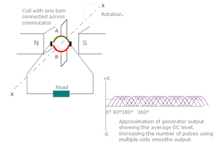
DC generator or direct current generator generates a voltage when speed and flux are met.This machine is called a unidirectional (dynamo).It consists of the same basic elements as a simple AC generator like the multi-turn coil rotating uniformly in a magnetic field .The output of which is a series of emf pulses, all in the same positive direction resulting in an average EMF developed across the load. Increasing the number of coils thereby smoothen the output providing more pulses at each revolution.

The generated voltage depends upon the number of poles  and armature winding turns. It  has armature with iron core and air gap which is uniform the vicinity of the center of the pole and which becomes larger as the pole tips are approached.This construction gives a uniform flux distribution under the main parts of the pole face with a reduction in the flux at pole tips.to produce an emf the conductor must cut the magnetic lines of force.The single coil is connected to two copper segments by carbon brushes. As before the output electromotive force is a result of the coil cutting across the lines of magnetic flux. With any inductive machine an emf will only be generated while the lines of flux are being cut. Stop the rotation at any angle and the output falls to zero.
AC GENERATOR
AC generator has an alternating current  a sinusoidal wave 


  This is not the same as adding more turns to a single coil, which would increase the emf output.The main difference between the DC generator and the AC generator is in their connections to the armature coil,where a commutator is now used . A commutator is a combination of a rotating split-ring and stationary metal brushes that reverses the polarity of the coil with respect to the external circuit, so that the negative half of the AC signal is reversed and made positive. The result is a pulsating  direct emf which rises and falls but never changes direction .  This pulsating emf can be smoothed out or become less pulsating until almost straight by using more than one coil rotating about the same axis, or by other electrical techniques

Emf generation of DC generator
Through commutation the current will be about the same axis

DC generator emf generation


  Generators are classified in terms of the field excitation and its connection to armature windings. Self -exited generators can only build-up its voltage when all the requirements are satisfied.