The Effects of electricity
Electricity is form of energy which could not be seen,but its presence could be detected due to numerous effects it has in our daily living.
1. Mechanical effect
An electric fan for ventilation through the rotation of its blades; A vacuum cleaner that cleans our floors with dirt's.These devices operate because of electricity. Mechanical effect of electricity is made possible by the use of the device called the motor. The electricity powers up the motor in order for it to make work for the benefit of man.
2. Chemical Effect
 The best example for a chemical effect of electricity is Electroplating. It involves the deposition of a thin protective layer onto a prepared metal surface, using electrochemical processes.Applications of electroplating can be observed from the household equipments ,kitchen utensils,instruments common steel bolts ,nuts and washers and and even a fashion wear such as bracelets, earrings and necklaces which could either be Gold plated, silver plated, . Aluminum parts and steel parts in lighting fixtures are also electroplated.
3.Thermal Effect
"A current of electricity passes over a conductor raises its temperature". That is why heating elements requires an alloy of metal to withstand intense heat without melting. This heating elements are installed in our electric cooker, iron and heater.
4.Magnetic effects
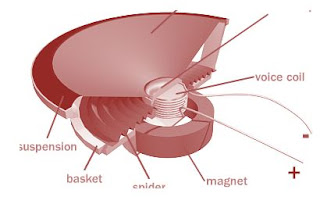 Speakers produces varying sounds because of magnetic effect. these devices have electromagnets and a permanent magnet .. These two magnets interact with each other. When the electrical current flowing through the voice coil changes direction, the coil's polar orientation reverses. This changes the magnetic forces between the electromagnet and the permanent magnet, moving the electromagnet and attached diaphragm back and forth . It pushes and pulls on the speaker cone producing a vibration of the air in front of the speaker creating sound waves.
 5. Physiological Effect
Are you familiar with a treatment known as "Shock Treatment or Shock Therapy" . This medical treatment is being utilized in rehabilitation centers to treat neurotic disorders
6.Photoelectric effect
Wondering how did the doors in malls hotels and other buildings and offices opens automatically as soon as you step the porch of these buildings? It is possible through photoelectric effect. These doors have "photo cells" This photocells have electrodes that are light sensitive that is used to operate a relay, which might turn a motor on to open a door or ring a bell in an alarm system. Same principle are also true in counting vehicles passing a road.
 7.Luminous Effect
" Light" this is the very common effect of electricity. If however after you had switched on the means of control and the room is still not illuminated,then you'll surely say, there's an absence of electricity. To layman's language it is called a black out or brown out. But what is being implied here actually is that there's no electrical current in the circuit.
Electricity is form of energy which could not be seen,but its presence could be detected due to numerous effects it has in our daily living.
1. Mechanical effect
An electric fan for ventilation through the rotation of its blades; A vacuum cleaner that cleans our floors with dirt's.These devices operate because of electricity. Mechanical effect of electricity is made possible by the use of the device called the motor. The electricity powers up the motor in order for it to make work for the benefit of man.
2. Chemical Effect
The best example for a chemical effect of electricity is Electroplating. It involves the deposition of a thin protective layer onto a prepared metal surface, using electrochemical processes.Applications of electroplating can be observed from the household equipments ,kitchen utensils,instruments common steel bolts ,nuts and washers and and even a fashion wear such as bracelets, earrings and necklaces which could either be Gold plated, silver plated, . Aluminum parts and steel parts in lighting fixtures are also electroplated.3.Thermal Effect
"A current of electricity passes over a conductor raises its temperature". That is why heating elements requires an alloy of metal to withstand intense heat without melting. This heating elements are installed in our electric cooker, iron and heater.
4.Magnetic effects
 Speakers produces varying sounds because of magnetic effect. these devices have electromagnets and a permanent magnet .. These two magnets interact with each other. When the electrical current flowing through the voice coil changes direction, the coil's polar orientation reverses. This changes the magnetic forces between the electromagnet and the permanent magnet, moving the electromagnet and attached diaphragm back and forth . It pushes and pulls on the speaker cone producing a vibration of the air in front of the speaker creating sound waves. 5. Physiological Effect
Are you familiar with a treatment known as "Shock Treatment or Shock Therapy" . This medical treatment is being utilized in rehabilitation centers to treat neurotic disorders
6.Photoelectric effect
Wondering how did the doors in malls hotels and other buildings and offices opens automatically as soon as you step the porch of these buildings? It is possible through photoelectric effect. These doors have "photo cells" This photocells have electrodes that are light sensitive that is used to operate a relay, which might turn a motor on to open a door or ring a bell in an alarm system. Same principle are also true in counting vehicles passing a road.

" Light" this is the very common effect of electricity. If however after you had switched on the means of control and the room is still not illuminated,then you'll surely say, there's an absence of electricity. To layman's language it is called a black out or brown out. But what is being implied here actually is that there's no electrical current in the circuit.