The familiarity of the few circuit building blocks is important in understanding complex circuits. In this post I will explain the most important ideas in DC circuits.
From my previous posts I discussed about the Ohms law . This is a continuation of the post about simple direct current circuits.
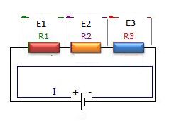
Resistors in series
A series circuit is one in which total line current passes through each and every conductor in the circuit. two or more electric component are considered to be in series in the same current flows through all these component
laws of Series circuit
1. current in all parts of the series circuit is the same
It=I1+I2+I3+In
2. voltage across a group of conductor connected in series is equal to the sum of the individual voltage across individual resistors
Et=E1+E2+E3+En
3. total resistance of a group of conductors connected in series is equal to the sum of the individual resistances
Rt=R1=R2+R3+Rn
Resistors in parallel
A parallel circuit is one in which current may flow through two or more independent branches.Two or more components are considered in parallel if the same voltage appears across all these components

laws of parallel circuits
1. total voltage of a parallel circuit is the same as across each branch of circuit
Et= E1=E2=E3=En
2.Total current is equal to the sum of individual branch currents
It=I1+I2+I3+In
3.The reciprocal of the total resistance of a number of resistors connected in parallel is equal to the sum of the reciprocals of the separate resistances.Total resistance is always less or approximately equal to the values of the smallest resistive branch
1/Rt=1/R1+1/R2+1/R3+1/Rn
Rt=1/(1/R1+1/R2+1/R3+1/Rn)
Note that : it is important to know that connecting additional resistors in series increases resistance, while connecting additional resistance in parallel decreases the total resistance.