Parallel RL circuit formula and diagram

The current through L will lag IR by 90 degrees . The resultant negative phase angle depends upon the relative values of R and XL. for R, E and R in phase . For XL , E and IL in quadratic lagging current.
As the circuit is inductive the phase angle is negative.
Parallel RL circuit Phasor Diagram

There cannot be a direct addition of IR and IL because of their 90 degree phase angle.
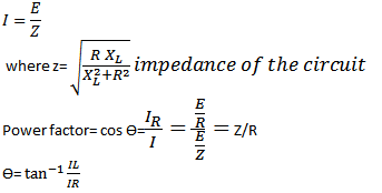
Parallel RL circuits formula