Tuesday, November 30, 2010

Power in parallel Circuits

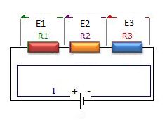
Power dissipated by each individual resistance is simply added to find the total power dissipated by the series circuit. This same procedure also applies to parallel circuits. If there are five resistive branches in a parallel circuit and each was dissipated 1 watt of power, the total power the circuit is 5 watts . The individual power dissipations of all resistors are added to find the total power dissipated.

Pt= P1+P2+P3....+Pn


Pt=1W+1W+1W+1W+1W=5W

power Calculations in parallel Circuits

power in parallel circuits formula


Where: I-current
            E-voltage
            R-Resistance


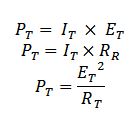
As an alternative method ,If you have already calculated the total or main line currents flowing in the circuits, the total circuit voltage,and /or the total circuit resistance, you can calculate the total power the circuit dissipates by using the three formulas listed above on the total circuit quantities.

alternative method power in parallel circuit


where:
It-total current
Et-Total voltage
Rt-Total Resistance
Pt-Total power

Monday, November 29, 2010

Series and parallel resistance circuit :explanation

The familiarity of the few circuit building blocks is important in  understanding complex circuits. In this post I will explain the most important ideas in  DC circuits.

From my previous posts I discussed about the Ohms law . This is a continuation of the post about  simple direct current circuits. 
   
Resistors in series
   A series circuit is one in which total line current passes through each and every conductor in the circuit. two or more electric component are considered to be in series in the same current flows through all these component
resistors in series diagram


laws of Series circuit
1. current in all parts of the series circuit is the same
It=I1+I2+I3+In
2. voltage across a group of conductor connected in series is equal to the sum of the individual voltage across individual resistors
Et=E1+E2+E3+En
3. total resistance of a group of conductors connected in series is equal to the sum of the individual resistances
Rt=R1=R2+R3+Rn

Resistors in parallel
  A parallel circuit is one in which current may flow through two or more independent branches.Two or more components are considered in parallel if the same voltage appears across all these components

resistors in parallel diagram


laws of parallel circuits
1. total voltage of a parallel circuit is the same as across each branch of circuit
Et= E1=E2=E3=En
2.Total current is equal to the sum of individual branch currents
It=I1+I2+I3+In
3.The reciprocal of the total resistance of a number of resistors connected in parallel is equal to the sum of the reciprocals of the separate resistances.Total resistance is always less or approximately equal to the values of the smallest resistive branch
1/Rt=1/R1+1/R2+1/R3+1/Rn
 Rt=1/(1/R1+1/R2+1/R3+1/Rn)

Note that : it is important to know that connecting additional resistors in series increases resistance, while connecting additional resistance in parallel decreases the total resistance.

Sunday, November 28, 2010

What are Motor controls and how they work

Motor controls a quick summary 
     Motor controls are those devices that operate electric motor particularly, those high powered electric motors used to operate machines like electric drilling machines, wood lathe machine, electric bending machine and those other machine used in the industry plant.
Motor controller


Motor controls can be divided into three major types;
1. Manual- The construction of the controllers here constitutes  only simple devices requiring the  operator  to go into the controller location to initiate the change in the state of the control system. the installation of the controller to the motor is simply done by connection of the switch in series withe the motor.

2. Semi-automatic-This type of controller is characterized by the use of push button, pressure switches , limit switches and other sensing devices to control the operation of magnetic contactor or starter. The operator must still initiate some actions such as starting and stopping but he does not have to go the location of the motor or the starter to perform the operation.


semiautomatic motor controls

3. Automatic- Similar to semiautomatic, an automatic controller  is characterized by the use of sensing devices.With an automatic control, the operator doest have to initiate certain actions. After that the operation is set , the system will continue to operate in its own.

Semi-automatic and automatic controllers are generally employed with an overload or low voltage release protection to shut down the system automatically for protection of the device and the operator.

     Motor Controls involves the use of the following devices like magnetic starters and push button station and  the use of cables to connect this devices. This cables maybe any of the following, BX cable ,loomex cable,steel conduit wiring.For push button stations it can be a start-stop, forward-reverse-stop push button and the start-jog-stop push button. For Push button types it can be a normally open or closed push button,stacked push button, push pull buttons and lighted push buttons. Push buttons  can make or break the connection in a control system.

Motor Controls are divided into the following
1.Motor controls for alternating current (AC)machines or motors
2 Motor controls for Direct current (DC) machines or motors

Saturday, November 27, 2010

A review Complex number

Complex number review 

   Complex number are usually discussed in the first part of advanced mathematics and here is a quick review about it.

Consider the equation
no solution equation in real number system
it has has NO SOLUTION in real number system.

complex number i or j
But in eighteenth century mathematician invented a   new number  "i"  which is defined by the property. this in turn , led to the development of complex numbers, which are numbers of the form a+bi .
   "a "and "b" are real numbers. But it can be also observed that every real number a is also a complex number because it can be written as a=a+0i. Thus ,the real numbers  are a subset of the complex numbers.

With these properties complex number can be now defined as.
---the combination of real and imaginary number which can be expressed in the form a+bi or a+jb where i or j=-1


Powers of i or j


powers of i or j
Note for  j^n
If n is divided by 4 and the result is 1 it follows j^4. if the result has a decimal value of (.75) if follows j^3.If (.50) it follows  j^2. If (.25) it follows j


Argand's diagram
argand's diagram


real axis


Forms of complex numbers -complex number can be expressed in different notations.
1.) rectangularr form  -complex number is denoted by its respective horizontal and vertical components.
         a+jb                              where:   a-real value
                                                          jb-imaginary axis 

2.) polar form - complex number can be denoted by the length  and the angle of its vector
         rÆŸ                                          where: r- magnitude
                                                                      ÆŸ - argument,degrees
3.) trigonometric form
           rcosÆŸ  +jsinÆŸ                     where: r-magnitude
                                                                    ÆŸ-argument,degrees
4.) Exponential form
complex number exponential form
                                            where: r-magnitude
                                                      ÆŸ-argument,degrees