Wednesday, March 28, 2012

Automatic Circuit Recloser

Recloser is a device that is used in over head distribution systems to interrupt the circuit to clear faults. Automatic reclosers have its electronic control senses and vacuum interrupters that automatically recloses to restore service  if a fault is temporary. There are several attempts that may be made to clear and reenergize the circuit and if the fault still exist the recloser locks out. Reclosers are made in single-phase and three-phase versions, and use  oil or vacuum interrupters.

Operation
Systems where a SCADA control interface capability is required in the use of automatic reclosers. The controls for the reclosers range from the original electromechanical systems to digital electronics. The operating sequence of all the reclosers can  be all fast, all delayed or any combination of fast followed by delayed up. Fast operations clear temporary faults before branch circuit line fuses are weakened. Delayed operations allow time for down time protective devices to clear so that permanent faults can be confined to smaller sections of the system.
automatic circuit recloser
Three Phase Vacuum Circuit Recloser
image credit: www.abb.com  
A complete electronic recloser package consists of the recloser which interrupts the circuit, an electronic control which senses over-currents and actuates the recloser and an interconnecting control cable.

Tripping and Closing
Recloser tripping and closing are initiated by signals from the electronic control. When fault currents in excess of the programmed minimum-trip value are detected in one or more phases, a signal from the control actuates a low energy tripper in the operating mechanism of the recloser to trip the opening springs and open the interrupter contacts. Closing energy and the force required to charge the opening springs is supplied by a high-voltage closing solenoid momentarily connected phase-to-phase through a high-voltage contactor.  At the programmed reclosing time, the control energizes a rotary solenoid in the operating mechanism which mechanically closes the closing solenoid contactor to connect the closing coil to its power source.  The energized closing coil pulls a plunger down, charging the opening springs.

Saturday, February 18, 2012

AC Circuit Phase Sequence

Phase sequence is the order in which the generated voltages in the phase winding of an alternator reach or  attain  their peak or maximum values. It is represented by the letters a, b, and c or the numbers 1, 2, 3 or by using double letter as ab, bc  and ca or  an, bn  and cn.

For instance , The three phase balanced voltages with their common magnitudes as K have sequence of a b c , then in complex form, 

Positive Phase Sequence 
ABC sequence  -  Va = Ka0˚ , Vb = a-120˚ and Vc = Ka-240˚

In this sequence Vb lags Va by 120˚ and Vc lags Vb by 120 or Vc lags Va by 240. The maximum value of Va comes first in the positive direction, next Vb and then Vc. 

ABC →BCA →CAB
AB - BC - CA → BC - CA - AB → CA - AB - BC
AN - BN - CN → BN - CN - AN → CN - AN - BN

Vector Representation

ABC Phase Sequence
 Sequence ABC  


BCA Phase Sequence
Sequence BCA
CAB Phase Sequence
Sequence CAB


Negative Phase sequence 
ACB sequence- Va = Ka0˚ , Vb = a-120˚ and Vc = Ka-240˚

Voltage Vc lags Va by 120˚ and voltage Vb lags Vc by 120˚

ACB →CBA →BAC
AB - CA - BC → CA- BC - AB → BC - AB - BA
AN - CN - BN → CN - BN - AN → BN - AN - CN

Vector representation
BAC Phase Sequence
Sequence BAC
CBA Phase Sequence
Sequence  CBA

ACB Phase Sequence
Sequence ACB

Assume a positive phase sequence if the phase sequence is not given . The three  phase alternators are designed to operate with positive phase sequence voltages.

Tuesday, January 17, 2012

Balanced Three phase AC circuit Delta connected

A balanced three phase AC circuit systems is energized by three equal alternating emf's of the same frequency but 120 degree apart. The phase impedance are equal. Also the currents are equal and 120 degree apart.
Three AC emf's differing in time phase by 120 degree
DELTA (MESH) CONNECTED SYSTEM
This type of connection is reffered to as 3 phase, 3 wire system. In this connection , the dissimilar ends of the 3 phase windings of a 3 phase ac generator are joined together,  for example the starting ends of one phase is joined to finishing end of the other phase so on. In other words the three winding's are joined in series to form a closed mesh. three leads are taken out from the juntions to serve as the generator terminals.
Delta mesh connected system
Delta connected System
Relationships: VØ = VL       :  IØ = IL/(3)   
 Where:
        VØ  - phase voltage
        IØ  - phase current
       VL -  line voltage
       IL -  line voltage

The three phase voltages of this circuit always sum to zero  Va + Vb + Vc =0

As seen from the diaram, there is only one phase winding completely included between any pair of terminals. Hence, in delta connection, the voltage between any pair of lines is equal of the phase voltage of the phase winding connected between the two lines considered.

Monday, January 16, 2012

Electronics :Traffic light Circuit


This is a two way continuous traffic light circuit which uses  LED, diodes and IC's . 
Usually most traffic light in the world is PLC controlled but this circuit is  simple  and easy to build . 

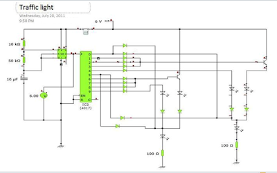
 In the image below is the schematic diagram of the project . I used Yenka Free Software to simulate and see if its properly working . You can download it free on Yenka website.

two way 555 traffic light circuit

The  clock pulses from the 555 astable circuit is sent into the 4017 decade counter . Each output becomes high in turn as the clock pulses are received. Appropriate outputs are combined with diodes to supply the amber and green LEDs. 
simple 2-waytraffic light circuit
components :
  • resistors: ,50k ohm, 10k ohm, two-100k ohm
  • capacitors: 10µF 16V radial
  • diodes:  16 pieces of 1N4148 
  • LEDs: 2 sets of ( red, amber or yellow, green)
  • IC:555 timer ,  4017 counter
  •  on/off switch
You can adjust the timing of light-shifting by adjusting the  value of the resistor in the astable circuit . 

Saturday, December 10, 2011

Plane Geometry Review : Triangle Area calculation


Area Formulas

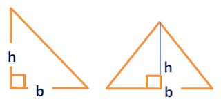
1.  Given base and altitude
Area triangle given base and height
Triangle: Given base and height
Area = 1/2 (b)(h)

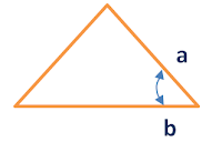
2. Given two sides and an Angle

area of triangle given 2 sides and an angle
 Triangle:  Given 2 sides and angle
Area = 1/2 (a) (b)sin Î¸

3. Given 3 sides
Area of triangle given 3 sides
Triangle Given 3 sides a,b,c

Area = sqrt (s(s-a)(s-b)(s-c))----->  Heron's Formula  
where s= (a+b+c)/2


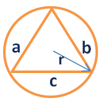
4. Triangle inscribed in a circle
area of Triangle inscribed in a cirle
r= radius of the circle 
Area = (a b c)/ 4r

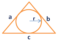
5. Given a circle inscribed in a Triangle

area of a triangle in a circle inscribing it
r = radius of the circle


Area  =  rs 
s = ( a+b+c/) 2


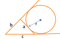
6. Circle escribed by the triangle

area of triangle given a circle escribing it
where a is the side tangent to the circle
Area =  r (s-a)
s = ( a+b+c/) 2