Showing posts with label AC Circuits. Show all posts

Saturday, February 18, 2012

AC Circuit Phase Sequence

Phase sequence is the order in which the generated voltages in the phase winding of an alternator reach or  attain  their peak or maximum values. It is represented by the letters a, b, and c or the numbers 1, 2, 3 or by using double letter as ab, bc  and ca or  an, bn  and cn.

For instance , The three phase balanced voltages with their common magnitudes as K have sequence of a b c , then in complex form, 

Positive Phase Sequence 
ABC sequence  -  Va = Ka0˚ , Vb = a-120˚ and Vc = Ka-240˚

In this sequence Vb lags Va by 120˚ and Vc lags Vb by 120 or Vc lags Va by 240. The maximum value of Va comes first in the positive direction, next Vb and then Vc. 

ABC →BCA →CAB
AB - BC - CA → BC - CA - AB → CA - AB - BC
AN - BN - CN → BN - CN - AN → CN - AN - BN

Vector Representation

ABC Phase Sequence
 Sequence ABC  


BCA Phase Sequence
Sequence BCA
CAB Phase Sequence
Sequence CAB


Negative Phase sequence 
ACB sequence- Va = Ka0˚ , Vb = a-120˚ and Vc = Ka-240˚

Voltage Vc lags Va by 120˚ and voltage Vb lags Vc by 120˚

ACB →CBA →BAC
AB - CA - BC → CA- BC - AB → BC - AB - BA
AN - CN - BN → CN - BN - AN → BN - AN - CN

Vector representation
BAC Phase Sequence
Sequence BAC
CBA Phase Sequence
Sequence  CBA

ACB Phase Sequence
Sequence ACB

Assume a positive phase sequence if the phase sequence is not given . The three  phase alternators are designed to operate with positive phase sequence voltages.

Tuesday, January 17, 2012

Balanced Three phase AC circuit Delta connected

A balanced three phase AC circuit systems is energized by three equal alternating emf's of the same frequency but 120 degree apart. The phase impedance are equal. Also the currents are equal and 120 degree apart.
Three AC emf's differing in time phase by 120 degree
DELTA (MESH) CONNECTED SYSTEM
This type of connection is reffered to as 3 phase, 3 wire system. In this connection , the dissimilar ends of the 3 phase windings of a 3 phase ac generator are joined together,  for example the starting ends of one phase is joined to finishing end of the other phase so on. In other words the three winding's are joined in series to form a closed mesh. three leads are taken out from the juntions to serve as the generator terminals.
Delta mesh connected system
Delta connected System
Relationships: VØ = VL       :  IØ = IL/(3)   
 Where:
        VØ  - phase voltage
        IØ  - phase current
       VL -  line voltage
       IL -  line voltage

The three phase voltages of this circuit always sum to zero  Va + Vb + Vc =0

As seen from the diaram, there is only one phase winding completely included between any pair of terminals. Hence, in delta connection, the voltage between any pair of lines is equal of the phase voltage of the phase winding connected between the two lines considered.

Friday, December 10, 2010

Parallel RC circuit formula and phasor diagram

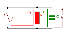
RC circuit in parallel formula and diagram
Parallel RC circuit connection diagram
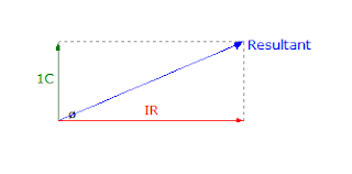
Currents in IR and IC are 90 degree out of phase and cannot be added directly. The total current or resultant will depend upon the resistance and R and the reactance ( AC reactance) of AC

Parallel RC circuit Phasor diagram :
Parallel RC circuit phasor diagram


As the reactance of C falls relative to resistance of R , so more current flows in the capacitor branch and the resultant phase angle increases

Parallel RC circuit formula :
Parallel RC circuit formula


Parallel RL circuits formula and Phasor diagram explanation

Parallel  RL circuit formula and diagram


Parallel RL circuits connection diagram

The current through L will lag  IR  by 90 degrees . The resultant negative phase angle  depends upon the relative values of R and XL. for R, E and R in phase . For  XL , E and IL in quadratic lagging current.
As  the circuit is inductive the phase angle is  negative.

Parallel RL circuit Phasor Diagram
Parallel RL circuit phasor diagram

There cannot be a direct addition of IR and IL because of their 90 degree phase angle. 

Parallel RL circuits formula

Parallel RL circuit formula

Parallel RL circuit formula proof


Thursday, December 9, 2010

Series RLC circuit formula explanation

Series RLC circuit diagram and formula
Series RLC  connection Diagram


Resistance ,inductance capacitance in series
  
formula resistance, capacitance and inductance in series


In RLC series circuit , the series current is common for Resistance, Capacitance and inductance . VR will be in phase width I. Whereas the voltage of Vc and VL will be 180 degree phase opposition, resulting in some cancellation.

Series RLC  Phasor Diagram
Series RLC phasor Diagram
The phasor diagram will produce the resultant circuit voltage and its phase angle. Positive angle indicate a greater inductive circuit influence and negative angle capacitive.

This is the corresponding formula for RLC circuit
Series RLC formula's


Series RLC Formulas

The formula for Series RC circuit with Phasor Diagram

Series RC circuit formula explanation

Series RC circuit diagram connection


 R- the resistance -opposition to current flow (ohms)Ω
C- capacitance-opposition to any change in voltage ,farad(f)
 VR=IR- voltage drop of the resistor
Vc= q/c=∫idt/c- voltage drop in the capacitor
     
     When a capacitor and a resistor  are in series current will flow to charge the capacitor .
 The two voltages VR and VC cannot be added directly and the phasor diagram is used  to find the resultant or the applied voltage amplitude and phase angle . 

Voltage VC can be found using Ohms law where VC = XC x I
The resultant or applied voltage is that which or developed across the circuit with these particular component values.  The resultant voltage can be greater than the individual values of VR and Vc   

As this is capacitive circuit the resultant voltage angle will lag the current I
Current I is shown as being in phase with VR . VC will lag I by 90.

Series RC circuit Phasor Diagram
series RC circuit Phasor diagram
Series RC circuit Formula
series RC circuit formula

Here are the Formulas and the proof solution for the formula in RC circuit:


series RC circuit formula proof solution

Series RC circuit Waveform
This is an example of a waveform produced by the   resultant voltage and corresponding resultant phase  angle.
series RC circuit generated waveform


Tuesday, November 23, 2010

Polyphase system: How Three phase sytem works?

Three Phase system

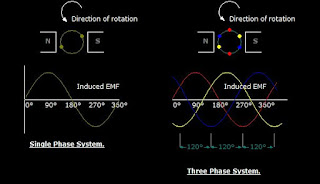
   A three phase circuit is energized by three alternating emf's of the same frequency and differing in time phase by 120 .The emfs are generated in three sets of armature coils in an ac generator. These three sets are 120 degree apart on the generator armature. The coils may all be brought of the generator to form three separate single phase circuits. however the coils are ordinarily interconnected either internally or externally to form  a three-wire or four wire system.

AC 3 three phase system
shows the generation of induced emf in 3 spaced coils with 120 degree phase difference
    The voltage in red coil  reaches a maximum cycle first,followed by coil in yellow, and then coil in blue for sequence ABC.The figure also shows the sine wave developed as the coil rotates.

the voltage phase sequence of the three phase system can be determined by the rotation of the alternator coils. At  counterclockwise rotation of the coils, the phase sequence is ABC. The opposite rotation gives the sequence CBA