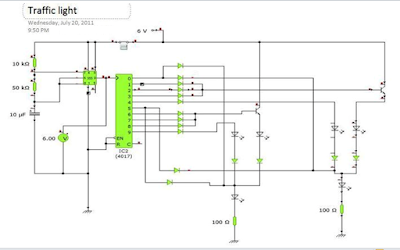
This is a two way continuous traffic light circuit which uses LED, diodes and IC's .
Usually most traffic light in the world is PLC controlled but this circuit is simple and easy to build .
In the image below is the schematic diagram of the project . I used Yenka Free Software to simulate and see if its properly working . You can download it free on Yenka website.
The clock pulses from the 555 astable circuit is sent into the 4017 decade counter . Each output becomes high in turn as the clock pulses are received. Appropriate outputs are combined with diodes to supply the amber and green LEDs.
components :
- resistors: ,50k ohm, 10k ohm, two-100k ohm
- capacitors: 10µF 16V radial
- diodes: 16 pieces of 1N4148
- LEDs: 2 sets of ( red, amber or yellow, green)
- IC:555 timer , 4017 counter
- on/off switch
You can adjust the timing of light-shifting by adjusting the value of the resistor in the astable circuit .

