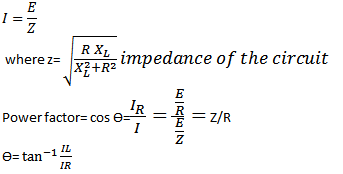
Series RC circuit formula explanation
R- the resistance -opposition to current flow (ohms)Ω
C- capacitance-opposition to any change in voltage ,farad(f)
VR=IR- voltage drop of the resistor
Vc= q/c=∫idt/c- voltage drop in the capacitor
When a capacitor and a resistor are in series current will flow to charge the capacitor .
The two voltages VR and VC cannot be added directly and the phasor diagram is used to find the resultant or the applied voltage amplitude and phase angle .
Voltage VC can be found using Ohms law where VC = XC x I
The resultant or applied voltage is that which or developed across the circuit with these particular component values. The resultant voltage can be greater than the individual values of VR and Vc
As this is capacitive circuit the resultant voltage angle will lag the current I
Current I is shown as being in phase with VR . VC will lag I by 90.
Series RC circuit Phasor Diagram
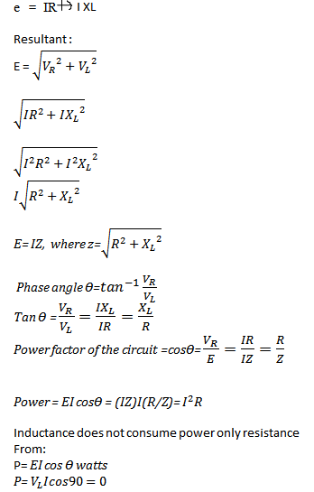
Series RC circuit Formula
Here are the Formulas and the proof solution for the formula in RC circuit:
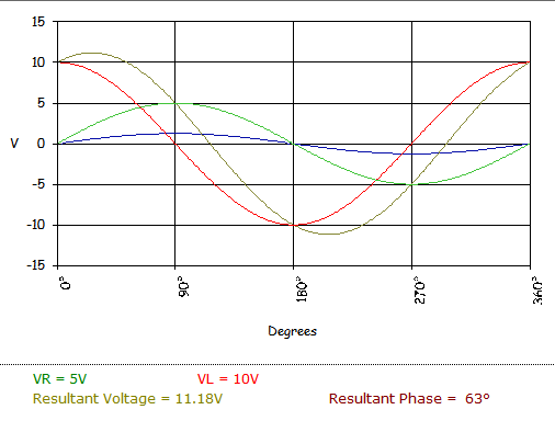
Series RC circuit Waveform
This is an example of a waveform produced by the resultant voltage and corresponding resultant phase angle.