Sunday, December 5, 2010

How to use multimeter as voltmeter DC voltage test


USE Multimeter as voltmeter
The DC voltmeter is used to measure direct current voltage or electrical pressure of a circuit. the unit of measure is in volt(V). Multi-meters can be used as voltmeter and this is done by connecting the instrument across the circuit . It requires correct application of the polarity. Your circuit must be powered up in conducting this test

Procedure:
  1.  Check the pointer of the multi-tester to zero 
  2. Set the knob to DCV. Set the voltage higher than the estimated value being measured. If the voltage range is unknown,get the estimate value by setting the knob at the top level (1000V) then choose a proper range for exact measurement
  3. Connect the multimeter across the circuit.Attach the black lead of the meter to the  to the negative (-) connection of the circuit ,and the red test lead to the positive (+)
  4. read the voltage value.
Attention:
  • Observe the correct polarity of the meter.
  • If the pointer deflects backward or the display to negative value disconnect the test probe immediately and reverse the connection of the pointer.
  • Always estimate the value of the voltage range to top level and gradually lower it until you can read it conveniently.
  • Do not touch the test probe.

How to use a multimeter as Ohmmeter

Ohmmeter- an ohmmeter  is used to measure resistance. Connected in parallel or across,  It can be used to check and measure the continuity of the circuit . When using  an ohmmeter it does not require correct application polarity.

Resistance test procedure:
    the purpose of the Ω test is to measure the resistance or checking out if the circuit is short or open . Here are the procedures in performing a resistance test using both analog and digital multimeter(DMM)

For Analog multi-meter
 use analog multimeter as ohmmeter
1. Set the knob to ohm (Ω).
2. Check the pointer of the multitester if it is set to infinite.
3. Set the multi-tester to the desired range. You can set the pointer initially at zero Ω by connecting the two leads of the instrument and adjusting the knob to be exactly zero.
4. Measure the resistance of  the component being measured. The reading is equivalent to the scale reading multiplied by the number indicated at the set range.  Ranges  are Ωx1, Ωx10 ,Ωx100, Ωx10k and Ωx1k 


how to use digital multimeter as ohmmeter         For Digital multimeter (DMM)
1. Turn off power and discharge all capacitors of the circuit  
2. Select "resistance" on the multimeter- You can switch to your designed ohm range position
3. Connect the test leads to the circuit to the device or circuit being measured
4  Read the resistance value on the digital display of the DMM


Note:
  • Do not touch the pins (metal part) of the test lead t o avoid reading error caused by the resistance of the human body
  • Don't make a resistance measurement while the circuit is with power. It may damage the meter by this improper operation
  • for analog multimeter ,reset the pointer to zero  when changing the range of the ohmmeter.

Wednesday, December 1, 2010

Using a Multimeter/multi-tester: Preliminary setup and Safety precautions

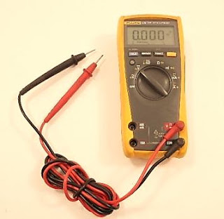
Multi-tester (VOM-volt/ohmeter) also called multimeter is designed to measure different magnitudes of electrical units:voltage,current and resistance. It incorporates the functions of a voltmeter,ohmmeter,and Milli-ammeter into one device. A multimeter maybe Digital (DVOM/DMM) or Analog.


Parts and functions of multi-tester
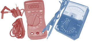
 parts of digital and analog multimeter
Digital multimeter        Analog multimeter
1.   Zero ohm adjuster- for analog multi-testers this part sets the  indicator of the left scale to zero
2.   Range Selector switch knob-this is a switch that is calibrated to select the proper range of the meter
3. Amperage terminal -plug in connection for red (positive) test lead for measuring amperes 
4   +V.Ω.f terminal(positive )- terminal for positive test probe.It is  used for most types of measurements.
5.   -COM terminal (negative,N)- a terminal for the negative test probe
6.   Home plate-Serves as the cover or panel for multi-tester
7.   Indicator pointer- It deflects a certain point and use as a reference of where to read the measurement
8.  Output socket- used for measuring special purpose such as high AC  voltage,intensity of sounds in decibel,etc
9. Range Scale- it indicates the test function and scale option
10. Display for Digital multi meter(DMM) -it displays the measurement reading. Usually have a four digit display with a +/- indicator. 
Preliminary setup before measurement

1. Before start measuring, make sure that the pointer stays at zero(0) position on the left end of the scale. If not,gently adjust the zero corrector with the use of screwdriver to set it to zero.

2.Select the proper range before measuring. Do not attempt to switch the range knob while  measuring. Disconnect the test leads first before switching the range knob as it may damage your multimeter. in determining a measuring range,select a higher voltage than the value to be measured as well as where the pointer of the meter moves to considerable extent. however,select the maximum range and measure in case the extent of value to be measures can not be predicted.

Precautions for safety measurement

1. Never use meter on the electric circuit that exceeds 3k VA.
2. Pay special attention when measuring the voltage of AC30 volts or DC60V or more to avoid injury.
3. Never apply an input signals exceeding the maximum rating input value.
4. Never use meter for measuring the line connected with equipment that generates induced or surge voltage since it may exceed the maximum allowable voltage.
5.  Never use meter if the meter or test leads are damaged or broken.
6.  Never use encase meter.
7.  Be sure to use fuse of the specified rating type.never use substitute of the use or never make a short circuit of the fuse.
8. Always keep your fingers behind the finger guards on the probe when making measurements.
9. Be sure to disconnect the test pins from the circuit when changing the function of the range.
10. Before starting measurement,make sure that the function and range are properly set in accordance with the measurement.
11. Never use meter with wet hands or in damp environment.
12. Never open tester case except when replacing batteries or fuses. Do not attempt any alteration of original specifications.
13. Never use test leads other than the specified test leads.
14. To ensure safety and maintain accuracy,calibrate and check the meter at least once a year.



Tuesday, November 30, 2010

Power in parallel Circuits

Power dissipated by each individual resistance is simply added to find the total power dissipated by the series circuit. This same procedure also applies to parallel circuits. If there are five resistive branches in a parallel circuit and each was dissipated 1 watt of power, the total power the circuit is 5 watts . The individual power dissipations of all resistors are added to find the total power dissipated.

Pt= P1+P2+P3....+Pn


Pt=1W+1W+1W+1W+1W=5W

power Calculations in parallel Circuits

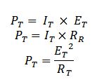
power in parallel circuits formula


Where: I-current
            E-voltage
            R-Resistance


As an alternative method ,If you have already calculated the total or main line currents flowing in the circuits, the total circuit voltage,and /or the total circuit resistance, you can calculate the total power the circuit dissipates by using the three formulas listed above on the total circuit quantities.

alternative method power in parallel circuit


where:
It-total current
Et-Total voltage
Rt-Total Resistance
Pt-Total power

Monday, November 29, 2010

Series and parallel resistance circuit :explanation

The familiarity of the few circuit building blocks is important in  understanding complex circuits. In this post I will explain the most important ideas in  DC circuits.

From my previous posts I discussed about the Ohms law . This is a continuation of the post about  simple direct current circuits. 
   
Resistors in series
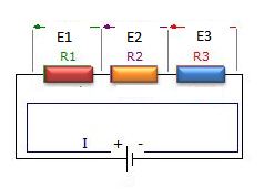
   A series circuit is one in which total line current passes through each and every conductor in the circuit. two or more electric component are considered to be in series in the same current flows through all these component
resistors in series diagram


laws of Series circuit
1. current in all parts of the series circuit is the same
It=I1+I2+I3+In
2. voltage across a group of conductor connected in series is equal to the sum of the individual voltage across individual resistors
Et=E1+E2+E3+En
3. total resistance of a group of conductors connected in series is equal to the sum of the individual resistances
Rt=R1=R2+R3+Rn

Resistors in parallel
  A parallel circuit is one in which current may flow through two or more independent branches.Two or more components are considered in parallel if the same voltage appears across all these components

resistors in parallel diagram


laws of parallel circuits
1. total voltage of a parallel circuit is the same as across each branch of circuit
Et= E1=E2=E3=En
2.Total current is equal to the sum of individual branch currents
It=I1+I2+I3+In
3.The reciprocal of the total resistance of a number of resistors connected in parallel is equal to the sum of the reciprocals of the separate resistances.Total resistance is always less or approximately equal to the values of the smallest resistive branch
1/Rt=1/R1+1/R2+1/R3+1/Rn
 Rt=1/(1/R1+1/R2+1/R3+1/Rn)

Note that : it is important to know that connecting additional resistors in series increases resistance, while connecting additional resistance in parallel decreases the total resistance.