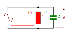
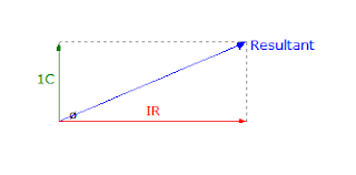
Power factor is an important aspect to consider in AC circuit, because any factor less than 1 means that the circuit wiring has to carry more current than what would be necessary with zero reactance in the circuit to deliver the same true power to the resistive load.
When expressed as fraction, the ratio between true power and apparent power is called the power factor of the circuit.
Kw
The power factor is given cosƟ = --------
KVA
in the case of single phase supply
VI KVAx1000
KVA= ---------- or I= -----------
1000 V
In case of three-phase supply
sqrt(3)VL IL KVAx 1000
KVA= -------------- or IL=-------------
1000 sqrt(3)VL
In the case of three phase supply
All current will cause losses in the supply and distribution system. A load with a power of 1.0 result in the most efficient loading of the supply and a load with a power of 0.5 will result in much higher losses in the supply such as an induction motor, power transformer, lighting ballast,welder or variable speed drive, switched mode power supply, discharge lighting or other electronic load.
The heating and lighting loads supplied from three-phase supply have power factors ranging from 0.95 to unity. But motor loads have usually low lagging power factor ranging from 0.5 to 0.9. Single phase motors may have a power factor of as low as 0.4 and electric welding units have even lower power factor of 0.2 or 0.3
A poor power factor due to an inductive load can be improved by the addition of power factor correction,but a poor power factor due to a distorted current waveform requires a change in equipment design or expensive harmonic filter s to gain an appreciable improvement. many inverters are quoted as having a power factor of better than 0.95 when in reality, true power factor is between 0.5 and 0.75. the Figure of 0.95 is based on the cosine of the angle between the voltage and current but does not take into account that the current waveform is discontinues and therefore contributes to increased losses on the supply
in each equation above, the KVA is directly proportional to the current. The chief disadvantage of a low power factor is that the current requires for a given power is very high. this fact leads to the following undesirable results.
1. Large KVA for a given amount of power.
All electric machines such as alternators, transformers, cables are limited in their current-carrying capacity by the permissible temperature rise which is proportional to I^2 .hence, they may all be fully loaded with respect to their rated KVA without delivering their full power.
2. Poor voltage regulation . When loading a low lagging power factor is switched on,there is a large voltage drop in the supply lines and transformers. this drop in voltage adversely affects the starting torque of motors and needs expensive voltage stabilizing equipment for keeping the consumers voltage fluctuations within the statutory limits


