Tuesday, November 23, 2010

ENGINEERING SOLUTIONS

ENGINEERING SOLUTIONS
I came across this blog just recently and I find this one very informative.This blog provides fresh graduates specially mechanical engineering, find a job in well reputed company . Tips and guidance published here will surely educate you in dealing with job interview.

Polyphase system: How Three phase sytem works?

Three Phase system

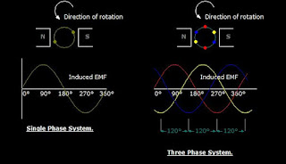
   A three phase circuit is energized by three alternating emf's of the same frequency and differing in time phase by 120 .The emfs are generated in three sets of armature coils in an ac generator. These three sets are 120 degree apart on the generator armature. The coils may all be brought of the generator to form three separate single phase circuits. however the coils are ordinarily interconnected either internally or externally to form  a three-wire or four wire system.

AC 3 three phase system
shows the generation of induced emf in 3 spaced coils with 120 degree phase difference
    The voltage in red coil  reaches a maximum cycle first,followed by coil in yellow, and then coil in blue for sequence ABC.The figure also shows the sine wave developed as the coil rotates.

the voltage phase sequence of the three phase system can be determined by the rotation of the alternator coils. At  counterclockwise rotation of the coils, the phase sequence is ABC. The opposite rotation gives the sequence CBA


Monday, November 8, 2010

Introduction to Ohm's law

                                                   
What is Ohm's Law ?
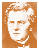
Georg Simon Ohm

In 1826 Georg Simon Ohm discovered that for metallic conductors there is substantially constant ratio of the potential difference between the ends of the conductor.
  Ohm's Law states that the current flowing in an electric circuit is directly proportional to the applied voltage and inversely proportional to the resistance of the material.
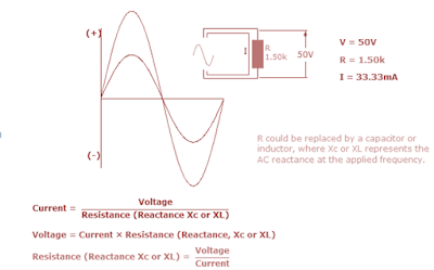
ohm's law equation
Ohm's Law equation
  
I- current
V-voltage
R- resistance


Ohm's law is explained by the following statement.

1. Current varies directly with applied voltage
    A change in the voltage applied to a circuit will  cause the current flowing in the circuit to change.  If the resistance is  constant, the current change will follow the pattern of the voltage change.  Doubling the potential difference doubles the current.

2. Current varies inversely with resistance
   Changing the resistance in a circuit will also cause a change in current flow. if the voltage applied to a circuit is held constant, and the resistance in the circuit is increased. With more opposition to current  flow in the circuit, the circuit current will decrease. On the other hand, if the resistance is decreased the amount of current flow in the circuit will be increased.


3. Voltage vs. current
voltage vs current graph
   The  relationship between voltage
and current can be graphically
 represented with this illustration.

thus:
  1. the higher the voltage, the larger the current
  2.the higher the resistance the lower the current

         AC Ohms Law
AC Ohms Law


Ohms law can also be applied in AC circuits.But alternating voltage and currents are always changing. From zero, current and voltage builds up and reach  its max peak in the positive value at 90 degrees and then back to zero and again to the negative peak value.
In this regard, Its only possible to calculate instantaneous values of voltage and current throughout its cycle.
For AC Ohms law can be expressed by the the same  equation , where R could be replaced by a  inductor or capacitor , where Xc or XL is the AC reactance
Ohms law circle form


Ohms Law Derived formulas formulas from 
Ohms law circle

V= I x R
I=  V/ R
R= V/ I


Saturday, November 6, 2010

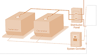
Generators in parallel

Why generators are in parallel?
here are some of the summarized  reasons:

1. Continuity of the service
2. Efficiency
3. maintenance and repair
4. Addition to plant ( provision or future expansion)
.
Parallel generator operation

Efficiency
In an electrical power generating system  the load fluctuates, usually reaching a minimum  during the night and having its peak value during day time.And with several machines required to supply the load, it becomes necessary to operate them in parallel so that their combined outputs may be transmitted from the same bus bars over outgoing lines.

Continuity of the service
Continuity of the service is not only desirable but also economic necessity.
When the load upon the system is small, it is undesirable from the standpoint of efficiency to have a large  generator lightly  loaded. its better to have a smaller generator operating near full load. if a shift in a load is made from a large generator to a small one or vice versa, the operation must be carried through  without interruption to service.

Expandability of the Plant
In expanding of the power supply system  it is often difficult to plan for anticipated load growth. If load projections are too aggressive, initial capital expenditures may be higher than necessary. If load projections are too low, the facility may be left without reliable standby power or may require expensive generator upgrades. By parallel connections of generators expansion of the generating system is not too complicated.

Maintenance and repair
As for parallel generators,  units can be taken out of service for repair or maintenance without losing standby  power for critical circuits. This feature enhances reliability and reduces the need to bring a backup generator within the site. Even the failures of standby generators are not very common,the built-in redundancy of a parallel system provides multiple layers of protection for critical circuits.

Friday, November 5, 2010

Introduction to DC Generator

GENERATOR is machine that converts mechanical energy to electrical energy.

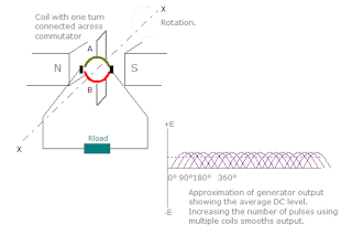
DC generator or direct current generator generates a voltage when speed and flux are met.This machine is called a unidirectional (dynamo).It consists of the same basic elements as a simple AC generator like the multi-turn coil rotating uniformly in a magnetic field .The output of which is a series of emf pulses, all in the same positive direction resulting in an average EMF developed across the load. Increasing the number of coils thereby smoothen the output providing more pulses at each revolution.

The generated voltage depends upon the number of poles  and armature winding turns. It  has armature with iron core and air gap which is uniform the vicinity of the center of the pole and which becomes larger as the pole tips are approached.This construction gives a uniform flux distribution under the main parts of the pole face with a reduction in the flux at pole tips.to produce an emf the conductor must cut the magnetic lines of force.The single coil is connected to two copper segments by carbon brushes. As before the output electromotive force is a result of the coil cutting across the lines of magnetic flux. With any inductive machine an emf will only be generated while the lines of flux are being cut. Stop the rotation at any angle and the output falls to zero.
AC GENERATOR
AC generator has an alternating current  a sinusoidal wave 


  This is not the same as adding more turns to a single coil, which would increase the emf output.The main difference between the DC generator and the AC generator is in their connections to the armature coil,where a commutator is now used . A commutator is a combination of a rotating split-ring and stationary metal brushes that reverses the polarity of the coil with respect to the external circuit, so that the negative half of the AC signal is reversed and made positive. The result is a pulsating  direct emf which rises and falls but never changes direction .  This pulsating emf can be smoothed out or become less pulsating until almost straight by using more than one coil rotating about the same axis, or by other electrical techniques

Emf generation of DC generator
Through commutation the current will be about the same axis

DC generator emf generation


  Generators are classified in terms of the field excitation and its connection to armature windings. Self -exited generators can only build-up its voltage when all the requirements are satisfied.