Friday, November 26, 2010

How are coils connected in an alternator ?

Alternator coil connections
  There are two ways of connecting the coils of the three phase AC generators  or alternator in a load. These are the wye or the star connection and the delta connection. Generally, generators are wye connected ( earth wire) but loads can be either delta or wye.

1. Star Connected, 4-wire Alternator
                                               iA
Star connected 4 wire alternator


iC


iB


This takes advantage of the fact that the sum of the three phase  current is zero
          iA +iB iC =0

When the generator has a balanced output and the loads connected to each phase are identical then the calculation of the voltages and current for, say the red phase can be applied equally to two other phases. The voltage in A,B,C are called phase voltages and are the potential difference developed between Vab, Vbc, Vac


2. Delta connected, 3-wire Alternator
    In this configuration the connection has no neutral line. The voltage between pair of lines are equal to the phase voltage of the generator and the line current is the  difference between the two phase currents.
    The line currents are the currents flowing into and from the load where the actual current is the addition of the two.
   For balanced poly-phase systems phases have  identical line voltages and currents.
border=
 iA  


iB


iC


delta connected alternator formulaThis takes advantage of the fact that the tree phase voltages always sum up to zero

          Va+Vb+Vc=0


Sources
Electrical engineering training series :Three phase alternator connection
Network analysis 2007
Thursday, November 25, 2010

Transformer operation and construction

Transformer: Basic operation and construction
  Transformer is an electrical device that converts voltage from one value to another that is, either from high voltage to lower voltage which is termed step- down transformer, or from lower voltage to higher voltage which is termed step up transformer. 


 The principle behind lowering or raising the voltage  is done through  magnetic induction between its coils. Changing current in the primary winding  creates  alternating magnetic field in its the core.  And  as the core multiplies this field and couples the most of the flux through the secondary transformer windings, It   creates an induction of alternating voltage or the electromotive force in each of the secondary coil.


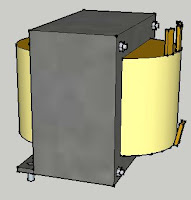
Core type transformer
A transformer is constructed with the following essential parts  :

1. Core (iron core or air core)
2. Windings ( primary winding or secondary winding)
3. Insulation (major insulation and minor insulation)
Transformer parts and function
The core is  made up of  of lamination   sheets. one of the best  used as core is silicon steel
 These sheets has its purpose:

a) to hold the windings in place
b) to serve as path for  magnetic circuit  or magnetic field
 The lamination sheets are pressed tightly together leaving no spaces between sheets.


  Another essential part of the transformer are the windings. Windings are made up of copper wire generally termed as magnetic wires. These wires are usually covered with varnish insulation. Other magnetic wires beside the varnished insulation are still covered with cotton and generally used for big transformer.

Transformer winding arrangement  Windings are composed of primary and the secondary winding. The primary winding is the one that is connected to the power supply , the purpose of which is to get the required power. On the other  hand, the secondary winding is the one connected to load and deliver the needed power. The secondary maybe one or more windings.


  The insulation is used to separate or insulate iron core as well as the windings. There are two types of insulation used in transformer,
a.) major insulation
b) minor insulation. the major insulation is used to insulate or separate the windings from the iron core and insulate or separate the primary winding from the secondary winding. The minor insulation on the other hand is used to insulate or separate one layer of turns to the  next layer.

Transformer Operation
  When the primary winding is plugged or connected to the power source, magnetic lines of force are developed around the windings and travels within the iron core. By electromagnetic induction principle, these magnetic lines of force travelling around the core induces another voltage to the secondary windings which gives the idea although the primary and the secondary windings are separated or not connected to each other, a lower or higher voltage can be produced in the secondary winding. in this operation of transformer, one must recall his knowledge of the principles  of electromagnetic induction.

Sources

Electrical Transformers Explained  How Is Electric Energy Produced

Tuesday, November 23, 2010

ENGINEERING SOLUTIONS

ENGINEERING SOLUTIONS
I came across this blog just recently and I find this one very informative.This blog provides fresh graduates specially mechanical engineering, find a job in well reputed company . Tips and guidance published here will surely educate you in dealing with job interview.

Polyphase system: How Three phase sytem works?

Three Phase system

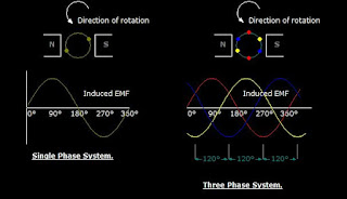
   A three phase circuit is energized by three alternating emf's of the same frequency and differing in time phase by 120 .The emfs are generated in three sets of armature coils in an ac generator. These three sets are 120 degree apart on the generator armature. The coils may all be brought of the generator to form three separate single phase circuits. however the coils are ordinarily interconnected either internally or externally to form  a three-wire or four wire system.

AC 3 three phase system
shows the generation of induced emf in 3 spaced coils with 120 degree phase difference
    The voltage in red coil  reaches a maximum cycle first,followed by coil in yellow, and then coil in blue for sequence ABC.The figure also shows the sine wave developed as the coil rotates.

the voltage phase sequence of the three phase system can be determined by the rotation of the alternator coils. At  counterclockwise rotation of the coils, the phase sequence is ABC. The opposite rotation gives the sequence CBA


Monday, November 8, 2010

Introduction to Ohm's law

                                                   
What is Ohm's Law ?
Georg Simon Ohm

In 1826 Georg Simon Ohm discovered that for metallic conductors there is substantially constant ratio of the potential difference between the ends of the conductor.
  Ohm's Law states that the current flowing in an electric circuit is directly proportional to the applied voltage and inversely proportional to the resistance of the material.
ohm's law equation
Ohm's Law equation
  
I- current
V-voltage
R- resistance


Ohm's law is explained by the following statement.

1. Current varies directly with applied voltage
    A change in the voltage applied to a circuit will  cause the current flowing in the circuit to change.  If the resistance is  constant, the current change will follow the pattern of the voltage change.  Doubling the potential difference doubles the current.

2. Current varies inversely with resistance
   Changing the resistance in a circuit will also cause a change in current flow. if the voltage applied to a circuit is held constant, and the resistance in the circuit is increased. With more opposition to current  flow in the circuit, the circuit current will decrease. On the other hand, if the resistance is decreased the amount of current flow in the circuit will be increased.


3. Voltage vs. current
voltage vs current graph
   The  relationship between voltage
and current can be graphically
 represented with this illustration.

thus:
  1. the higher the voltage, the larger the current
  2.the higher the resistance the lower the current

         AC Ohms Law
AC Ohms Law


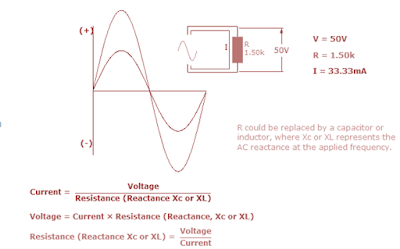
Ohms law can also be applied in AC circuits.But alternating voltage and currents are always changing. From zero, current and voltage builds up and reach  its max peak in the positive value at 90 degrees and then back to zero and again to the negative peak value.
In this regard, Its only possible to calculate instantaneous values of voltage and current throughout its cycle.
For AC Ohms law can be expressed by the the same  equation , where R could be replaced by a  inductor or capacitor , where Xc or XL is the AC reactance
Ohms law circle form


Ohms Law Derived formulas formulas from 
Ohms law circle

V= I x R
I=  V/ R
R= V/ I