Power factor is an important aspect to consider in AC circuit, because any factor less than 1 means that the circuit wiring has to carry more current than what would be necessary with zero reactance in the circuit to deliver the same true power to the resistive load.
When expressed as fraction, the ratio between true power and apparent power is called the power factor of the circuit.
Kw
The power factor is given cosƟ = --------
KVA
in the case of single phase supply
VI KVAx1000
KVA= ---------- or I= -----------
1000 V
In case of three-phase supply
sqrt(3)VL IL KVAx 1000
KVA= -------------- or IL=-------------
1000 sqrt(3)VL
In the case of three phase supply
All current will cause losses in the supply and distribution system. A load with a power of 1.0 result in the most efficient loading of the supply and a load with a power of 0.5 will result in much higher losses in the supply such as an induction motor, power transformer, lighting ballast,welder or variable speed drive, switched mode power supply, discharge lighting or other electronic load.
The heating and lighting loads supplied from three-phase supply have power factors ranging from 0.95 to unity. But motor loads have usually low lagging power factor ranging from 0.5 to 0.9. Single phase motors may have a power factor of as low as 0.4 and electric welding units have even lower power factor of 0.2 or 0.3
A poor power factor due to an inductive load can be improved by the addition of power factor correction,but a poor power factor due to a distorted current waveform requires a change in equipment design or expensive harmonic filter s to gain an appreciable improvement. many inverters are quoted as having a power factor of better than 0.95 when in reality, true power factor is between 0.5 and 0.75. the Figure of 0.95 is based on the cosine of the angle between the voltage and current but does not take into account that the current waveform is discontinues and therefore contributes to increased losses on the supply
in each equation above, the KVA is directly proportional to the current. The chief disadvantage of a low power factor is that the current requires for a given power is very high. this fact leads to the following undesirable results.
1. Large KVA for a given amount of power.
All electric machines such as alternators, transformers, cables are limited in their current-carrying capacity by the permissible temperature rise which is proportional to I^2 .hence, they may all be fully loaded with respect to their rated KVA without delivering their full power.
2. Poor voltage regulation . When loading a low lagging power factor is switched on,there is a large voltage drop in the supply lines and transformers. this drop in voltage adversely affects the starting torque of motors and needs expensive voltage stabilizing equipment for keeping the consumers voltage fluctuations within the statutory limits
Friday, December 10, 2010
RLC parallel circuit formula and Phasor diagram
RLC in parallel


![]()
RCL parallel circuit can be considered as two reactance's XC and XL where the currents are in phase opposition in parallel with the resistor.

Through the use of the phasor diagram the effective total resistance can be found . It can be observed that IR is at the base of the right triangle and IL minus IC minus IL forming the perpendicular.
The amplitude of the resultant current is the hypotenuse.
To calculate the resultant we use the Pythagorean theorem . Ic and IL are 180 degree out of phase therefore cancel out. The resultant current is the difference between the two.

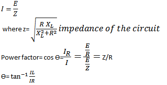
Impedance phase angle is calculated from the difference between IL and IC divided by IR
Parallel RC circuit formula and phasor diagram
RC circuit in parallel formula and diagram
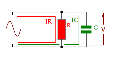
Parallel RC circuit Phasor diagram :


Currents in IR and IC are 90 degree out of phase and cannot be added directly. The total current or resultant will depend upon the resistance and R and the reactance ( AC reactance) of AC
Parallel RC circuit Phasor diagram :

As the reactance of C falls relative to resistance of R , so more current flows in the capacitor branch and the resultant phase angle increases
Parallel RC circuit formula :
Parallel RL circuits formula and Phasor diagram explanation
Parallel RL circuit formula and diagram

The current through L will lag IR by 90 degrees . The resultant negative phase angle depends upon the relative values of R and XL. for R, E and R in phase . For XL , E and IL in quadratic lagging current.
As the circuit is inductive the phase angle is negative.
Parallel RL circuit Phasor Diagram

There cannot be a direct addition of IR and IL because of their 90 degree phase angle.
Parallel RL circuits formula

Thursday, December 9, 2010
Series RLC circuit formula explanation
Series RLC circuit diagram and formula

Resistance ,inductance capacitance in series

Series RLC Phasor Diagram

The phasor diagram will produce the resultant circuit voltage and its phase angle. Positive angle indicate a greater inductive circuit influence and negative angle capacitive.
This is the corresponding formula for RLC circuit

Series RLC Formulas
The formula for Series RC circuit with Phasor Diagram
Series RC circuit formula explanation

R- the resistance -opposition to current flow (ohms)Ω
R- the resistance -opposition to current flow (ohms)Ω
C- capacitance-opposition to any change in voltage ,farad(f)
VR=IR- voltage drop of the resistor
Vc= q/c=∫idt/c- voltage drop in the capacitor
When a capacitor and a resistor are in series current will flow to charge the capacitor .
The two voltages VR and VC cannot be added directly and the phasor diagram is used to find the resultant or the applied voltage amplitude and phase angle .
Voltage VC can be found using Ohms law where VC = XC x I
The resultant or applied voltage is that which or developed across the circuit with these particular component values. The resultant voltage can be greater than the individual values of VR and Vc
As this is capacitive circuit the resultant voltage angle will lag the current I
Current I is shown as being in phase with VR . VC will lag I by 90.
Series RC circuit Phasor Diagram

Series RC circuit Formula

Here are the Formulas and the proof solution for the formula in RC circuit:

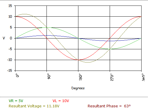
Series RC circuit Waveform
This is an example of a waveform produced by the resultant voltage and corresponding resultant phase angle.

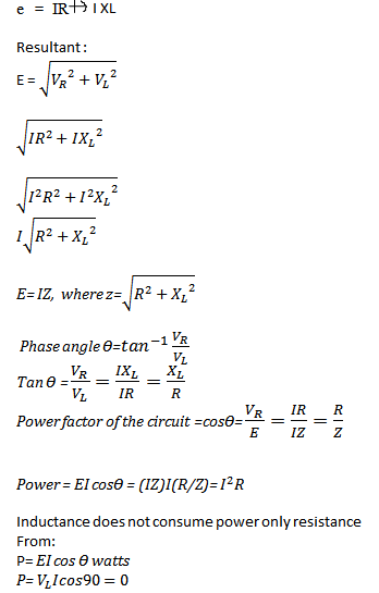
Analyze the formula for Series RL circuit and its Phasor Diagram
Series RL circuit

R- the resistance -opposition to current flow (ohms)Ω
L- Inductance -opposition to any change
XL- inductive resistance
VR=I R volts
VL=I XL volts
XL = inductance reactance (ohms) Ω
= 2πfL= ωL
Voltage developed across R and L cannot be added directly. The phasor diagram is used to show the resultant voltage and phase angle.The resultant or the applied voltage will lead the current I which is given an arbitrary value in the instance to show that is in phase with VR
Phasor diagram Series RL circuit:

Series RL Circuit generated Waveform:
The larger the relative value of the XL to R the closer the resultant phase angle willl be 90 degrees which is an indication of the amount of inductance in the circuit.
Tuesday, December 7, 2010
What are the effects of Electricity
The Effects of electricity
Electricity is form of energy which could not be seen,but its presence could be detected due to numerous effects it has in our daily living.
1. Mechanical effect
An electric fan for ventilation through the rotation of its blades; A vacuum cleaner that cleans our floors with dirt's.These devices operate because of electricity. Mechanical effect of electricity is made possible by the use of the device called the motor. The electricity powers up the motor in order for it to make work for the benefit of man.
2. Chemical Effect
 The best example for a chemical effect of electricity is Electroplating. It involves the deposition of a thin protective layer onto a prepared metal surface, using electrochemical processes.Applications of electroplating can be observed from the household equipments ,kitchen utensils,instruments common steel bolts ,nuts and washers and and even a fashion wear such as bracelets, earrings and necklaces which could either be Gold plated, silver plated, . Aluminum parts and steel parts in lighting fixtures are also electroplated.
3.Thermal Effect
"A current of electricity passes over a conductor raises its temperature". That is why heating elements requires an alloy of metal to withstand intense heat without melting. This heating elements are installed in our electric cooker, iron and heater.
4.Magnetic effects
 Speakers produces varying sounds because of magnetic effect. these devices have electromagnets and a permanent magnet .. These two magnets interact with each other. When the electrical current flowing through the voice coil changes direction, the coil's polar orientation reverses. This changes the magnetic forces between the electromagnet and the permanent magnet, moving the electromagnet and attached diaphragm back and forth . It pushes and pulls on the speaker cone producing a vibration of the air in front of the speaker creating sound waves.
 5. Physiological Effect
Are you familiar with a treatment known as "Shock Treatment or Shock Therapy" . This medical treatment is being utilized in rehabilitation centers to treat neurotic disorders
6.Photoelectric effect
Wondering how did the doors in malls hotels and other buildings and offices opens automatically as soon as you step the porch of these buildings? It is possible through photoelectric effect. These doors have "photo cells" This photocells have electrodes that are light sensitive that is used to operate a relay, which might turn a motor on to open a door or ring a bell in an alarm system. Same principle are also true in counting vehicles passing a road.
 7.Luminous Effect
" Light" this is the very common effect of electricity. If however after you had switched on the means of control and the room is still not illuminated,then you'll surely say, there's an absence of electricity. To layman's language it is called a black out or brown out. But what is being implied here actually is that there's no electrical current in the circuit.
Electricity is form of energy which could not be seen,but its presence could be detected due to numerous effects it has in our daily living.
1. Mechanical effect
An electric fan for ventilation through the rotation of its blades; A vacuum cleaner that cleans our floors with dirt's.These devices operate because of electricity. Mechanical effect of electricity is made possible by the use of the device called the motor. The electricity powers up the motor in order for it to make work for the benefit of man.
2. Chemical Effect
The best example for a chemical effect of electricity is Electroplating. It involves the deposition of a thin protective layer onto a prepared metal surface, using electrochemical processes.Applications of electroplating can be observed from the household equipments ,kitchen utensils,instruments common steel bolts ,nuts and washers and and even a fashion wear such as bracelets, earrings and necklaces which could either be Gold plated, silver plated, . Aluminum parts and steel parts in lighting fixtures are also electroplated.3.Thermal Effect
"A current of electricity passes over a conductor raises its temperature". That is why heating elements requires an alloy of metal to withstand intense heat without melting. This heating elements are installed in our electric cooker, iron and heater.
4.Magnetic effects
 Speakers produces varying sounds because of magnetic effect. these devices have electromagnets and a permanent magnet .. These two magnets interact with each other. When the electrical current flowing through the voice coil changes direction, the coil's polar orientation reverses. This changes the magnetic forces between the electromagnet and the permanent magnet, moving the electromagnet and attached diaphragm back and forth . It pushes and pulls on the speaker cone producing a vibration of the air in front of the speaker creating sound waves. 5. Physiological Effect
Are you familiar with a treatment known as "Shock Treatment or Shock Therapy" . This medical treatment is being utilized in rehabilitation centers to treat neurotic disorders
6.Photoelectric effect
Wondering how did the doors in malls hotels and other buildings and offices opens automatically as soon as you step the porch of these buildings? It is possible through photoelectric effect. These doors have "photo cells" This photocells have electrodes that are light sensitive that is used to operate a relay, which might turn a motor on to open a door or ring a bell in an alarm system. Same principle are also true in counting vehicles passing a road.

" Light" this is the very common effect of electricity. If however after you had switched on the means of control and the room is still not illuminated,then you'll surely say, there's an absence of electricity. To layman's language it is called a black out or brown out. But what is being implied here actually is that there's no electrical current in the circuit.
Using multimeter VOM as voltmeter for ACV test
The Ac voltmeter is used to measure alternative current voltage or electrical pressure of a circuit. This instrument is connected across the circuit and it does not require correct application of the polarity . The unit of measure is volt(V).
Note;
- If the voltage range is unknown get the estimate value by setting the knob at the top level or should be at 1000 V before measuring AC voltage,then adjust or lower the range until you could read it conveniently.
- Do not touch the test probe.
Procedure:
- set the knob of your multimeter to AC V
- Choose the proper range .The numbers indicated in the multimeter are the maximum voltage reading for the range.
- Connect the test probe in the component being measured
- Read the voltage value on the display
Sunday, December 5, 2010
Using multimeter VOM as Ammeter
The DC ammeter- is used to measure the direct current of a circuit. The unit of measure is ampere (A). An multimeter can be used as ammeter by connecting it in series with the circuit. It requires correct application and polarity to measure the current.
Procedure:
1. Check the pointer of the meter if it set to zero
2. Set the knob at DC and set it to the desired ampere range.There are different ranges including 250 mA ,25mA 2.5mA and 50uA .For safety, set the knob at the top level (250mA ) to gain rough value when the current range is unknown. If you can not read it conveniently try to lower the range of the meter gradually in accordance with the first rough data for precise measurement.
3. Connect the test leads in series with the circuit. Apply the pin of the red lead to positive and black one to negative.
4. Read the current value in the display
Note
- Do not touch the test probe.
- Observe the polarity of the meter if the pointer deflects backward or the value to be negative,remove the connection immediately and reverse the connection of the test probe.
How to use multimeter as voltmeter DC voltage test
USE Multimeter as voltmeter
The DC voltmeter is used to measure direct current voltage or electrical pressure of a circuit. the unit of measure is in volt(V). Multi-meters can be used as voltmeter and this is done by connecting the instrument across the circuit . It requires correct application of the polarity. Your circuit must be powered up in conducting this test
Procedure:
- Check the pointer of the multi-tester to zero
- Set the knob to DCV. Set the voltage higher than the estimated value being measured. If the voltage range is unknown,get the estimate value by setting the knob at the top level (1000V) then choose a proper range for exact measurement
- Connect the multimeter across the circuit.Attach the black lead of the meter to the to the negative (-) connection of the circuit ,and the red test lead to the positive (+)
- read the voltage value.
Attention:
- Observe the correct polarity of the meter.
- If the pointer deflects backward or the display to negative value disconnect the test probe immediately and reverse the connection of the pointer.
- Always estimate the value of the voltage range to top level and gradually lower it until you can read it conveniently.
- Do not touch the test probe.
How to use a multimeter as Ohmmeter
Ohmmeter- an ohmmeter is used to measure resistance. Connected in parallel or across, It can be used to check and measure the continuity of the circuit . When using an ohmmeter it does not require correct application polarity.
Resistance test procedure:
the purpose of the Ω test is to measure the resistance or checking out if the circuit is short or open . Here are the procedures in performing a resistance test using both analog and digital multimeter(DMM)
For Analog multi-meter
 1. Set the knob to ohm (Ω).
2. Check the pointer of the multitester if it is set to infinite.
3. Set the multi-tester to the desired range. You can set the pointer initially at zero Ω by connecting the two leads of the instrument and adjusting the knob to be exactly zero.
4. Measure the resistance of the component being measured. The reading is equivalent to the scale reading multiplied by the number indicated at the set range. Ranges are Ωx1, Ωx10 ,Ωx100, Ωx10k and Ωx1k
 For Digital multimeter (DMM)
1. Turn off power and discharge all capacitors of the circuit
2. Select "resistance" on the multimeter- You can switch to your designed ohm range position
3. Connect the test leads to the circuit to the device or circuit being measured
4 Read the resistance value on the digital display of the DMM
Resistance test procedure:
the purpose of the Ω test is to measure the resistance or checking out if the circuit is short or open . Here are the procedures in performing a resistance test using both analog and digital multimeter(DMM)
For Analog multi-meter
2. Check the pointer of the multitester if it is set to infinite.
3. Set the multi-tester to the desired range. You can set the pointer initially at zero Ω by connecting the two leads of the instrument and adjusting the knob to be exactly zero.
4. Measure the resistance of the component being measured. The reading is equivalent to the scale reading multiplied by the number indicated at the set range. Ranges are Ωx1, Ωx10 ,Ωx100, Ωx10k and Ωx1k
 For Digital multimeter (DMM)
1. Turn off power and discharge all capacitors of the circuit
2. Select "resistance" on the multimeter- You can switch to your designed ohm range position
3. Connect the test leads to the circuit to the device or circuit being measured
4 Read the resistance value on the digital display of the DMM
Note:
- Do not touch the pins (metal part) of the test lead t o avoid reading error caused by the resistance of the human body
- Don't make a resistance measurement while the circuit is with power. It may damage the meter by this improper operation
- for analog multimeter ,reset the pointer to zero when changing the range of the ohmmeter.
Wednesday, December 1, 2010
Using a Multimeter/multi-tester: Preliminary setup and Safety precautions
Multi-tester (VOM-volt/ohmeter) also called multimeter is designed to measure different magnitudes of electrical units:voltage,current and resistance. It incorporates the functions of a voltmeter,ohmmeter,and Milli-ammeter into one device. A multimeter maybe Digital (DVOM/DMM) or Analog.
1. Zero ohm adjuster- for analog multi-testers this part sets the indicator of the left scale to zero
Parts and functions of multi-tester
 |
| Digital multimeter Analog multimeter |
2. Range Selector switch knob-this is a switch that is calibrated to select the proper range of the meter
3. Amperage terminal -plug in connection for red (positive) test lead for measuring amperes
4 +V.Ω.f terminal(positive )- terminal for positive test probe.It is used for most types of measurements.
4 +V.Ω.f terminal(positive )- terminal for positive test probe.It is used for most types of measurements.
5. -COM terminal (negative,N)- a terminal for the negative test probe
6. Home plate-Serves as the cover or panel for multi-tester
7. Indicator pointer- It deflects a certain point and use as a reference of where to read the measurement
8. Output socket- used for measuring special purpose such as high AC voltage,intensity of sounds in decibel,etc
9. Range Scale- it indicates the test function and scale option
10. Display for Digital multi meter(DMM) -it displays the measurement reading. Usually have a four digit display with a +/- indicator.
Preliminary setup before measurement
1. Before start measuring, make sure that the pointer stays at zero(0) position on the left end of the scale. If not,gently adjust the zero corrector with the use of screwdriver to set it to zero.
2.Select the proper range before measuring. Do not attempt to switch the range knob while measuring. Disconnect the test leads first before switching the range knob as it may damage your multimeter. in determining a measuring range,select a higher voltage than the value to be measured as well as where the pointer of the meter moves to considerable extent. however,select the maximum range and measure in case the extent of value to be measures can not be predicted.
Precautions for safety measurement
1. Never use meter on the electric circuit that exceeds 3k VA.
2. Pay special attention when measuring the voltage of AC30 volts or DC60V or more to avoid injury.
3. Never apply an input signals exceeding the maximum rating input value.
4. Never use meter for measuring the line connected with equipment that generates induced or surge voltage since it may exceed the maximum allowable voltage.
5. Never use meter if the meter or test leads are damaged or broken.
6. Never use encase meter.
7. Be sure to use fuse of the specified rating type.never use substitute of the use or never make a short circuit of the fuse.
8. Always keep your fingers behind the finger guards on the probe when making measurements.
9. Be sure to disconnect the test pins from the circuit when changing the function of the range.
10. Before starting measurement,make sure that the function and range are properly set in accordance with the measurement.
11. Never use meter with wet hands or in damp environment.
12. Never open tester case except when replacing batteries or fuses. Do not attempt any alteration of original specifications.
13. Never use test leads other than the specified test leads.
14. To ensure safety and maintain accuracy,calibrate and check the meter at least once a year.
Tuesday, November 30, 2010
Power in parallel Circuits
Power dissipated by each individual resistance is simply added to find the total power dissipated by the series circuit. This same procedure also applies to parallel circuits. If there are five resistive branches in a parallel circuit and each was dissipated 1 watt of power, the total power the circuit is 5 watts . The individual power dissipations of all resistors are added to find the total power dissipated.
Pt= P1+P2+P3....+Pn
Pt=1W+1W+1W+1W+1W=5W
power Calculations in parallel Circuits

Where: I-current
E-voltage
R-Resistance
As an alternative method ,If you have already calculated the total or main line currents flowing in the circuits, the total circuit voltage,and /or the total circuit resistance, you can calculate the total power the circuit dissipates by using the three formulas listed above on the total circuit quantities.
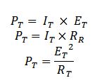
where:
It-total current
Et-Total voltage
Rt-Total Resistance
Pt-Total power
Pt= P1+P2+P3....+Pn
Pt=1W+1W+1W+1W+1W=5W
power Calculations in parallel Circuits
Where: I-current
E-voltage
R-Resistance
As an alternative method ,If you have already calculated the total or main line currents flowing in the circuits, the total circuit voltage,and /or the total circuit resistance, you can calculate the total power the circuit dissipates by using the three formulas listed above on the total circuit quantities.
where:
It-total current
Et-Total voltage
Rt-Total Resistance
Pt-Total power
Monday, November 29, 2010
Series and parallel resistance circuit :explanation
The familiarity of the few circuit building blocks is important in understanding complex circuits. In this post I will explain the most important ideas in DC circuits.

laws of parallel circuits
From my previous posts I discussed about the Ohms law . This is a continuation of the post about simple direct current circuits.
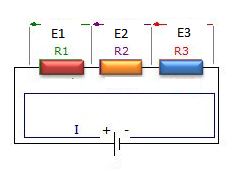
Resistors in series
A series circuit is one in which total line current passes through each and every conductor in the circuit. two or more electric component are considered to be in series in the same current flows through all these component
laws of Series circuit
laws of Series circuit
1. current in all parts of the series circuit is the same
It=I1+I2+I3+In
2. voltage across a group of conductor connected in series is equal to the sum of the individual voltage across individual resistors
Et=E1+E2+E3+En
3. total resistance of a group of conductors connected in series is equal to the sum of the individual resistances
Rt=R1=R2+R3+Rn
Resistors in parallel
A parallel circuit is one in which current may flow through two or more independent branches.Two or more components are considered in parallel if the same voltage appears across all these components
laws of parallel circuits
1. total voltage of a parallel circuit is the same as across each branch of circuit
Et= E1=E2=E3=En
2.Total current is equal to the sum of individual branch currents
It=I1+I2+I3+In
3.The reciprocal of the total resistance of a number of resistors connected in parallel is equal to the sum of the reciprocals of the separate resistances.Total resistance is always less or approximately equal to the values of the smallest resistive branch
1/Rt=1/R1+1/R2+1/R3+1/Rn
Rt=1/(1/R1+1/R2+1/R3+1/Rn)
Rt=1/(1/R1+1/R2+1/R3+1/Rn)
Note that : it is important to know that connecting additional resistors in series increases resistance, while connecting additional resistance in parallel decreases the total resistance.
Sunday, November 28, 2010

What are Motor controls and how they work
Motor controls a quick summary
Motor controls are those devices that operate electric motor particularly, those high powered electric motors used to operate machines like electric drilling machines, wood lathe machine, electric bending machine and those other machine used in the industry plant.

Motor controls can be divided into three major types;
1. Manual- The construction of the controllers here constitutes only simple devices requiring the operator to go into the controller location to initiate the change in the state of the control system. the installation of the controller to the motor is simply done by connection of the switch in series withe the motor.
2. Semi-automatic-This type of controller is characterized by the use of push button, pressure switches , limit switches and other sensing devices to control the operation of magnetic contactor or starter. The operator must still initiate some actions such as starting and stopping but he does not have to go the location of the motor or the starter to perform the operation.

3. Automatic- Similar to semiautomatic, an automatic controller is characterized by the use of sensing devices.With an automatic control, the operator doest have to initiate certain actions. After that the operation is set , the system will continue to operate in its own.
Semi-automatic and automatic controllers are generally employed with an overload or low voltage release protection to shut down the system automatically for protection of the device and the operator.
Motor Controls involves the use of the following devices like magnetic starters and push button station and the use of cables to connect this devices. This cables maybe any of the following, BX cable ,loomex cable,steel conduit wiring.For push button stations it can be a start-stop, forward-reverse-stop push button and the start-jog-stop push button. For Push button types it can be a normally open or closed push button,stacked push button, push pull buttons and lighted push buttons. Push buttons can make or break the connection in a control system.
Motor Controls are divided into the following
1.Motor controls for alternating current (AC)machines or motors
2 Motor controls for Direct current (DC) machines or motors
Motor controls are those devices that operate electric motor particularly, those high powered electric motors used to operate machines like electric drilling machines, wood lathe machine, electric bending machine and those other machine used in the industry plant.

Motor controls can be divided into three major types;
1. Manual- The construction of the controllers here constitutes only simple devices requiring the operator to go into the controller location to initiate the change in the state of the control system. the installation of the controller to the motor is simply done by connection of the switch in series withe the motor.
2. Semi-automatic-This type of controller is characterized by the use of push button, pressure switches , limit switches and other sensing devices to control the operation of magnetic contactor or starter. The operator must still initiate some actions such as starting and stopping but he does not have to go the location of the motor or the starter to perform the operation.
3. Automatic- Similar to semiautomatic, an automatic controller is characterized by the use of sensing devices.With an automatic control, the operator doest have to initiate certain actions. After that the operation is set , the system will continue to operate in its own.
Semi-automatic and automatic controllers are generally employed with an overload or low voltage release protection to shut down the system automatically for protection of the device and the operator.
Motor Controls involves the use of the following devices like magnetic starters and push button station and the use of cables to connect this devices. This cables maybe any of the following, BX cable ,loomex cable,steel conduit wiring.For push button stations it can be a start-stop, forward-reverse-stop push button and the start-jog-stop push button. For Push button types it can be a normally open or closed push button,stacked push button, push pull buttons and lighted push buttons. Push buttons can make or break the connection in a control system.
Motor Controls are divided into the following
1.Motor controls for alternating current (AC)machines or motors
2 Motor controls for Direct current (DC) machines or motors
Saturday, November 27, 2010
A review Complex number
Complex number review
Complex number are usually discussed in the first part of advanced mathematics and here is a quick review about it.
Consider the equation
 it has has NO SOLUTION in real number system.

But in eighteenth century mathematician invented a new number "i" which is defined by the property. this in turn , led to the development of complex numbers, which are numbers of the form a+bi .
"a "and "b" are real numbers. But it can be also observed that every real number a is also a complex number because it can be written as a=a+0i. Thus ,the real numbers are a subset of the complex numbers.
With these properties complex number can be now defined as.
---the combination of real and imaginary number which can be expressed in the form a+bi or a+jb where i or j=-1
Powers of i or j
 Note for j^n
If n is divided by 4 and the result is 1 it follows j^4. if the result has a decimal value of (.75) if follows j^3.If (.50) it follows j^2. If (.25) it follows j
Argand's diagram

real axis
Forms of complex numbers -complex number can be expressed in different notations.
1.) rectangularr form -complex number is denoted by its respective horizontal and vertical components.
a+jb where: a-real value
jb-imaginary axis
2.) polar form - complex number can be denoted by the length and the angle of its vector
r∠Ɵ where: r- magnitude
Ɵ - argument,degrees
3.) trigonometric form
rcosƟ +jsinƟ where: r-magnitude
Ɵ-argument,degrees
4.) Exponential form
 where: r-magnitude
Complex number are usually discussed in the first part of advanced mathematics and here is a quick review about it.
Consider the equation
But in eighteenth century mathematician invented a new number "i" which is defined by the property. this in turn , led to the development of complex numbers, which are numbers of the form a+bi .
"a "and "b" are real numbers. But it can be also observed that every real number a is also a complex number because it can be written as a=a+0i. Thus ,the real numbers are a subset of the complex numbers.
With these properties complex number can be now defined as.
---the combination of real and imaginary number which can be expressed in the form a+bi or a+jb where i or j=-1
Powers of i or j
If n is divided by 4 and the result is 1 it follows j^4. if the result has a decimal value of (.75) if follows j^3.If (.50) it follows j^2. If (.25) it follows j
Argand's diagram

real axis
Forms of complex numbers -complex number can be expressed in different notations.
1.) rectangularr form -complex number is denoted by its respective horizontal and vertical components.
a+jb where: a-real value
jb-imaginary axis
2.) polar form - complex number can be denoted by the length and the angle of its vector
r∠Ɵ where: r- magnitude
Ɵ - argument,degrees
3.) trigonometric form
rcosƟ +jsinƟ where: r-magnitude
Ɵ-argument,degrees
4.) Exponential form
Ɵ-argument,degrees
Friday, November 26, 2010
How are coils connected in an alternator ?
Alternator coil connections
There are two ways of connecting the coils of the three phase AC generators or alternator in a load. These are the wye or the star connection and the delta connection. Generally, generators are wye connected ( earth wire) but loads can be either delta or wye.
1. Star Connected, 4-wire Alternator
iA

iC
iB
![]() This takes advantage of the fact that the sum of the three phase current is zero
This takes advantage of the fact that the sum of the three phase current is zero
iA +iB iC =0
When the generator has a balanced output and the loads connected to each phase are identical then the calculation of the voltages and current for, say the red phase can be applied equally to two other phases. The voltage in A,B,C are called phase voltages and are the potential difference developed between Vab, Vbc, Vac
2. Delta connected, 3-wire Alternator
In this configuration the connection has no neutral line. The voltage between pair of lines are equal to the phase voltage of the generator and the line current is the difference between the two phase currents.
The line currents are the currents flowing into and from the load where the actual current is the addition of the two.
For balanced poly-phase systems phases have identical line voltages and currents.

iA
iB
iC
 This takes advantage of the fact that the tree phase voltages always sum up to zero
Va+Vb+Vc=0
Sources
Electrical engineering training series :Three phase alternator connection
Network analysis 2007
There are two ways of connecting the coils of the three phase AC generators or alternator in a load. These are the wye or the star connection and the delta connection. Generally, generators are wye connected ( earth wire) but loads can be either delta or wye.
1. Star Connected, 4-wire Alternator
iA

iC
iB
 This takes advantage of the fact that the sum of the three phase current is zero
iA +iB iC =0
When the generator has a balanced output and the loads connected to each phase are identical then the calculation of the voltages and current for, say the red phase can be applied equally to two other phases. The voltage in A,B,C are called phase voltages and are the potential difference developed between Vab, Vbc, Vac
2. Delta connected, 3-wire Alternator
In this configuration the connection has no neutral line. The voltage between pair of lines are equal to the phase voltage of the generator and the line current is the difference between the two phase currents.
The line currents are the currents flowing into and from the load where the actual current is the addition of the two.
For balanced poly-phase systems phases have identical line voltages and currents.

iA
iB
iC
This takes advantage of the fact that the tree phase voltages always sum up to zeroVa+Vb+Vc=0
Sources
Electrical engineering training series :Three phase alternator connection
Network analysis 2007
Thursday, November 25, 2010
Transformer operation and construction
Transformer: Basic operation and construction
Transformer is an electrical device that converts voltage from one value to another that is, either from high voltage to lower voltage which is termed step- down transformer, or from lower voltage to higher voltage which is termed step up transformer.
The principle behind lowering or raising the voltage is done through magnetic induction between its coils. Changing current in the primary winding creates alternating magnetic field in its the core. And as the core multiplies this field and couples the most of the flux through the secondary transformer windings, It creates an induction of alternating voltage or the electromotive force in each of the secondary coil.
A transformer is constructed with the following essential parts :
1. Core (iron core or air core)
2. Windings ( primary winding or secondary winding)
3. Insulation (major insulation and minor insulation)
 The core is made up of of lamination sheets. one of the best used as core is silicon steel
These sheets has its purpose:
a) to hold the windings in place
b) to serve as path for magnetic circuit or magnetic field
The lamination sheets are pressed tightly together leaving no spaces between sheets.
Another essential part of the transformer are the windings. Windings are made up of copper wire generally termed as magnetic wires. These wires are usually covered with varnish insulation. Other magnetic wires beside the varnished insulation are still covered with cotton and generally used for big transformer.
 Windings are composed of primary and the secondary winding. The primary winding is the one that is connected to the power supply , the purpose of which is to get the required power. On the other hand, the secondary winding is the one connected to load and deliver the needed power. The secondary maybe one or more windings.
The insulation is used to separate or insulate iron core as well as the windings. There are two types of insulation used in transformer,
a.) major insulation
b) minor insulation. the major insulation is used to insulate or separate the windings from the iron core and insulate or separate the primary winding from the secondary winding. The minor insulation on the other hand is used to insulate or separate one layer of turns to the next layer.
Transformer Operation
When the primary winding is plugged or connected to the power source, magnetic lines of force are developed around the windings and travels within the iron core. By electromagnetic induction principle, these magnetic lines of force travelling around the core induces another voltage to the secondary windings which gives the idea although the primary and the secondary windings are separated or not connected to each other, a lower or higher voltage can be produced in the secondary winding. in this operation of transformer, one must recall his knowledge of the principles of electromagnetic induction.
Sources
Transformer is an electrical device that converts voltage from one value to another that is, either from high voltage to lower voltage which is termed step- down transformer, or from lower voltage to higher voltage which is termed step up transformer.
The principle behind lowering or raising the voltage is done through magnetic induction between its coils. Changing current in the primary winding creates alternating magnetic field in its the core. And as the core multiplies this field and couples the most of the flux through the secondary transformer windings, It creates an induction of alternating voltage or the electromotive force in each of the secondary coil.
 |
2. Windings ( primary winding or secondary winding)
3. Insulation (major insulation and minor insulation)

a) to hold the windings in place
b) to serve as path for magnetic circuit or magnetic field
The lamination sheets are pressed tightly together leaving no spaces between sheets.
Another essential part of the transformer are the windings. Windings are made up of copper wire generally termed as magnetic wires. These wires are usually covered with varnish insulation. Other magnetic wires beside the varnished insulation are still covered with cotton and generally used for big transformer.
 Windings are composed of primary and the secondary winding. The primary winding is the one that is connected to the power supply , the purpose of which is to get the required power. On the other hand, the secondary winding is the one connected to load and deliver the needed power. The secondary maybe one or more windings.
The insulation is used to separate or insulate iron core as well as the windings. There are two types of insulation used in transformer,
a.) major insulation
b) minor insulation. the major insulation is used to insulate or separate the windings from the iron core and insulate or separate the primary winding from the secondary winding. The minor insulation on the other hand is used to insulate or separate one layer of turns to the next layer.
Transformer Operation
When the primary winding is plugged or connected to the power source, magnetic lines of force are developed around the windings and travels within the iron core. By electromagnetic induction principle, these magnetic lines of force travelling around the core induces another voltage to the secondary windings which gives the idea although the primary and the secondary windings are separated or not connected to each other, a lower or higher voltage can be produced in the secondary winding. in this operation of transformer, one must recall his knowledge of the principles of electromagnetic induction.
Sources